BACK HOME

The Nyköping talk was a disaster. The organiser had no remote control, but worse, their computer had a mind of its own. My carefully sorted pictures came up out of control, some were distorted and the last ones was absent.

However the room was filled to capacity and public was kind and even seemed to enjoy my improvised talk.

I was guided out of town. My guide was told not to go under low bridges as I was trailing my boat with the mast standing. He misunderstood the instructions.

A big bang made me jump as we passed under a bridge. It was all dark. At 50 km/hour my mast had hit the bridge. The shroud knots had  some flex and no damage was done. A good test for stormy waters.

Apart from little incidents like the above one a trailable boat is a wounderful thing. It allowed me to bring my boat up to Stockholm over the week end. Not to mention last year when I trailed her to Ireland for a good start on my transat. She came back to Sweden from Martinique in a container and again I trailed her from Göteborg to Västervik.

An outher time I trailed an outher boat to La Trinite France then sailed her to Newfoundland. From St. Johns she went on the road to Maine where I sailed her a few weeks before bringing her by car to Newport R.I. where she was sailed. Finally on the road again to New Jersey and shipping her back to Sweden.

Trailing extends your cruising ground enormously

I strongly suggest a trailer able boat. Give her a strong bottom that you can let her down on concrete stone and other hard surfaces. Mine has a bronze sole, strong, antifouling, and a good earth plate for your lightning conductor.

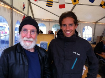
Below a bonus picture. Me and my co-author selling the new book Den unge den gamle och havet at the boat show.

Regards Yrvind.
FROM THE BOAT SHOW

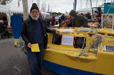
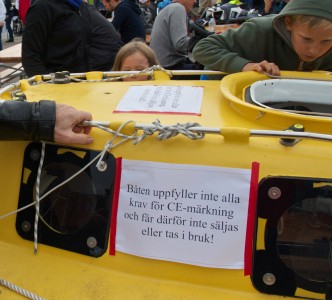
To day was the last day from the boat show. Beppe, my webmaster took two pictures of the boat with the sign from The European boating direktivs message. It translates that its illegal to sell the boat and to use it. Crazy ideas in a crazy world.

Click once or twice to enlarge.

The text enlarged

Tomorrow I will give a talk in Nyköping.

Regards Yrvind

SPREADING SMALL BOAT LORE

Tomorrow wendsday the 29th of August I leave for Stockholm. I will exhibit “YRVIND.COM” the boat I last year sailed to Martinique in at “ALLT PÅ SJÖN” in Gustavsberg Värmdö.

I will also sell the new book “Den unge, den gamle och havet” . On saturday and sunday I will be joined by Captain Thomas Grahn, the young, my co-author.

On Monday 3rd of September I will give an illustrated slide show in Nyköping at NK-villan. I will bring my boat and books.

I hope to see many people with a positive interest in small boat cruising.

Regards Yrvind.
UPPDATE

There has been some progress on the C.B. It is strong but heavyer than I like. Last boat became to heavy. But to cite Churchill when his wife nagged him about spending to much money. We must save she said. No Churchill said we must make more money.

On this line I have given this present boat a lot of displacement. The big modell, the 1/8 was test sailed with 1850 kilos scaled up displacement.

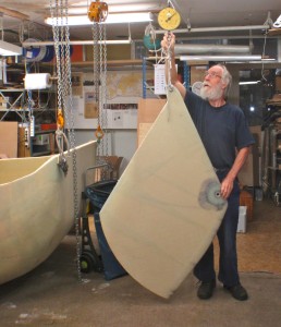
All structures brake down. It is only a question of time. If I will not have the means of leaving from the southern hemispere I will leave from Kinsale Ireland like last time. That means I have to be at sea for maybee 18 months. In that long time in rough weather a lot of wear will occour. Therefore I now give her scantlings to match. The C.B. weighs in at 15 kilos.

To enlarge click once or twice.

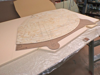
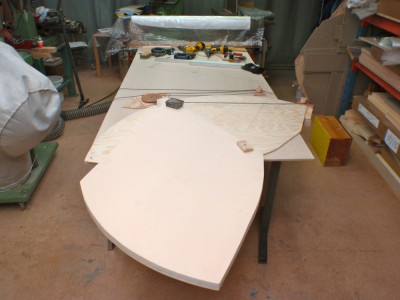
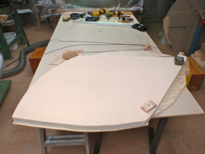
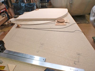
Here is the start of the C.B-case.

Here a picture of he pattern.

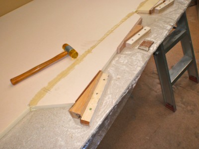
As can be seen I have to glue on additional pieces of Divinycell H130. To clamp them I use wedges.

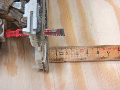
It is handy to be able to cut out the shape on the table. To be able to do that I have shortend the jiggsaw blade to the thickness of the Divinycell 2cm.

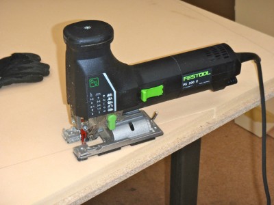
Here cutting. The saw blade cut through the Divinycell but not the table.

I thank Petter for helping me to laminate.

To be continued…

Regards Yrvind.
AN IDEA FOR REDUCING THE FORCES ON THE RIG

The main forces on the mast is compression due to the haliard and bending due to wind. The bending force is reduced by reefing, but there is still a lot of compression force. The masts ability to withstand the compression decreases by the square of the lenght that is compressed.

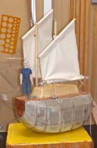
Last night I said to myself that a good way to reduce that force is to mowe down the point where sail is attatched to the mast when reefing. If in strong winds it is lowered half the distance the compression force is reduced to a quarter. If the sail is attatched to the mast without a halyard it is halfed again.

That way there is only one eight of the compression on the mast left. Weight and wind resistance of the halyard is also gone. A gain well worth considering.

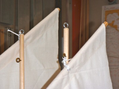
Below are two pictures illustrating my chain of thougt. Click once or twice to enlarge.

A close up.

The masts will be short between 3 and 4 meter 10 to 13 feet and distance between thema only 1.2 meter or four feet. It is therefore very simple to use the masts as suport for steps to a temporary ladder to use when lowering the sail.

To be continued…

Regards Yrvind.
MORE WORK ON THE C.B.

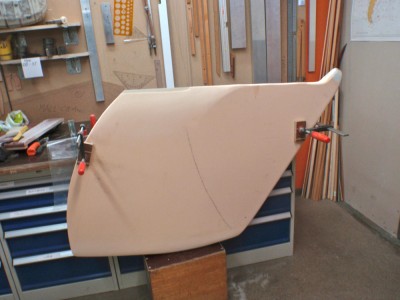
I keep working on the C.B. I like to make it as good as I can. It is excessive, but in a world were yachts are done to minimum standard- except the finish which Neptune dont care about- it is nice to have something to be proud of. Besides it is also nice when you are out there to know that what ever the sea will throw at you you do not have to worry but can sleep peacefully.

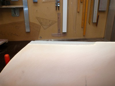
The C.B. is now shaped. The trailing edge is very thin therefore I have shaved away the Divinycell there and replaced it with epoxy thickened with migrofibers.

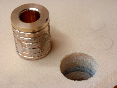
I have also made a bronze bearing for the axis. The pin diameter will be 18 mm close to 3/4 inch.

The below picture shows the shaped C.B. Click once or twice to enlarge.

The below picture shows the shaved away Divinycell.

The below picture shows the pin bronze bearing. Some gassfibre reenforcement can be seen in the hole, more will be addded higher up.

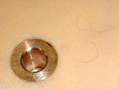
The below picture shows the bronze pin bearing epoxy-glued in position. Later some Divinycell will be routed out and replaced with glass fibre reenforcement.

To be continued…

Regards Yrvind.
A DETAIL

I am still working on the C.B. The control lines, upphaul and downhaul needs a reliabel point of attachment. The distance from that point to the rollers should be as small as possible. It is also important that the knot or splice is beyond the fitting as not to add to the lenght. A knot two inches long on each side of the fitting means four inches and if there are two fittings worse. It is worse becouse the whole centerboard case will be that much bigger and if you build a ten feet ocean going  boat it is nice to conserve space.

The following pictures show my solution. Click once or twice to enlarge.

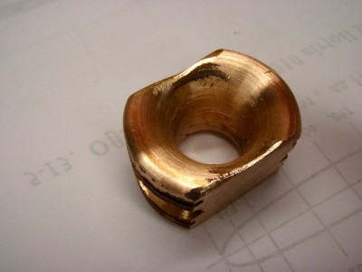
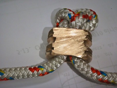
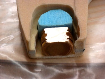
The above shows a  thimble I made of bronze. I will encapsulate it on the top of the C.B. the surface is increased to get more contact with the epoxy. One more square centimeter means 300 kilo more load can be absorbed.

The hole is just big enough for two 10 mm ropes to pass through. A figure eight knot acts as a stop.

The fitting in its position ready to take the thickend glassfibre reenforced epoxy. The blue stuff is styrofoam preventing the epoxy to fill the space where the rope  and the knot later will be.

To be continued…

Regards Yrvind.

C.B. FINAL MOCK UP AND NACA PROFIL

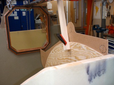
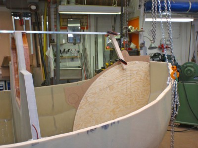
This is the final mock up. Small corrections will be made and transfered to the real C.B.-case. On the aft top end a step will be made. It is the inspection hatch that fills two functions. Click once or twice to enlarge picture.

This is the same motif seen from a different angle. The aluminum profil indicates the top of the deck house.

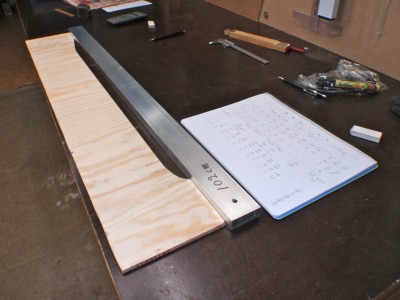
Above is a picture of the pattern of the NACA-profil that will guide me shaping the C.B. The hydrodynamic properties are compromised in favour of strenght. To get a good nos radie I have chosen a NACA 0020, that is 20% thick, nos radie 8.6 mm. The real C.B. is 43 mm without lamination. The virtuel chord is therefore 215 mm. The chord of thereal  C.B. is more than 700 mm. I have therefore split the profile at its maximum thickness, that is 30% from the leading edge and inserted a parrallel section of the missing lenght.

To be continued…

Regards Yrvind

MORE C.B. MOCK UP

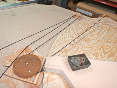
The surface shape of the C.B. is now cut. Time for one more mock up. Everything was OK in the hull. However now I had to figure out how the control lines were going to find their way to the deck. I did not want them inside the boat becouse that would bring in water in one form or other. The original plan was to conduct the down-haul in a pipe straight up to the top of the deck-house. But there was the sliding hatch making that impossible. It had to come out foreward of the deck-house.

Picture one show the C.B. in the down position. click once or twice to enlarge.

Picture two shows the C.B in the up position.

Picture 3 shows the drawing of the sliding hatch. It is a pen drawing look close.

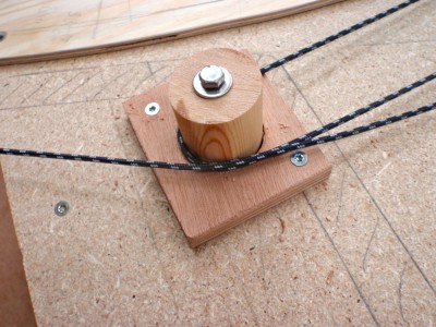
Picture 4 shows a piece of plywood around the roller preventing the rope from getting stuck between the roller and the C.B.-case. One of these anti-stuck pieces on each side of the C.B.-case.

Picture 5 shows the dawn-haul roller. It has a much bigger diameter. The reason is to lift up the rope some centimeters to clear the top of the C.B. Here the C.B. is in the down position. The lower rope dissapears up through the deck when the board is raised. It is the other rope that has to stay clear as the board mowes foreward.

For service, to change rope etc. there is a slot in the deck leading to the C.B.-case. At the back above the big diameter roller there is a service hatch.

To bee continued…

Regards Yrvind.