YRVIND TEN – THE SAILS

THE SAILS OF YRVIND TEN

The sails of YRVIND TEN has four corners. There is a 2.5 meter boom at the bottom and a 2.3 meter yard at the top – they are parallel. The halyard is placed 40 % from the leading edge on the yard. The booms downhaul is placed 20 % from the leading edge. The sail is not attached to the mast except by the halyard. Most people will classify it as a balanced lug but it isn’t necessarily so. For example a different downhaul fastened at the stem can be placed further aft along the boom when sailing downwind. In that configuration the sail becomes a square sail and creates a lifting force. Good to have in windy weather.

A square sail has the highest lifting force of all planforms when running free. Besides that there are some other interesting aspects of a square sail running down wind.

Ever wondered why the shaft or rachis of a flying feather is not in the middle? Well foils have their center of lift located a third from the leading edge. The shaft is located were the biggest forces are.

Ever been curios of the way a leaf falls, why it moves from side to side keeping the same side down? The reason is as soon air starts flow over its surfaces a center of effort is created about 30% from the leading edge. That side starts moving up against gravity. That causes that reduces the speed of the flow. After it stops it falls the other way because it is now slanted that way. A new leading edge is created and the process is repeated. The result is that it falls down in a zigzag fashion.

The same happens to a square sail running downwind. As long as the wind is from exactly behind the pressure is in the middle of the sail. As soon as the wind start to come in from one side the center of effort moves to that side bringing the boat back on its course, making the boat self-steer downwind. A boat has more inertia than a leaf therefore the zigzag movement is in slow motion. Matt Layden uses that effect to self-steer his Paradox downwind. First time he entered the Water Tribe Everglades Challenge he did win by more than a day.

Sailing in deep water I always use a preventer. A preventer is a line that leads forward from the end of the boom. That way the boom cannot accidently swing back and cause trouble. In this configuration the boom is already at the steam and forward of my steam there is nothing. But by fastening the preventer on the opposite side of the downhaul it locks the boom. The sheet and the preventer pulls back. Between them the downhaul pulls forward thus locking the sail.

YRVIND TEN has two masts side by side. The masts are connected with a bar that has both of its ends fixed to the masts. That creates a system that can take up torsion and bending. The two masts thus support each other in all directions. Any force on one mast is being taken up by the whole system. One mast can therefore take up nearly twice the load compared to if it had not been connected to its Siamese twin. The structure also makes a good climbing frame.

Out there no one will take me to court if I use two halyards on the same sail. By moving the halyards point of attachment on the yard I can convert the sail from lugsail to square sail and in strong winds running down wind that configuration makes sense.

Each sail is 6 square meter or about 65 square feet. It is only in light wind I will use the two sails or 12 square meters. I do not drive my boats at maximum speed nor do I drive my car at maximum speed one soon tires of it and sailing or driving at full speed creates a lot of disadvantages like danger and break downs and discomfort and fatigue. Speed is for novices. After the initial thrill focusing on the same speed gets boring even if it is fast.

The relation between speed and power is not always appreciated. Here is an example from one of Phillips Birt books: A 3-ton powerboat of 25 feet waterline length needs

3 hp to reach 5 knots

6.5 hp to reach 6 knots

15 hp to reach 7 knots and

26 hp to reach 8 knots.

That is to increase speed by 60% power needs to be increased by 867%.

I do not sail to reach the other shore as fast as possible. I sail to have deep water under my keel. In other words I like to be at sea.

1974 I sailed BRIS from St Helena to Martinique about 3800 miles in 48 days averaging 80 miles a day crossing the doldrums without engine. I had a small double ender of about 20 feet waterline length and a displacement of about 1400 kilos. The interesting thing I used only 4 square meter sail and was perfectly happy.

2011 I sailed 15 feet YRVIND.COM boat from Madeira to Martinique taking 45 days I used about 2 square meters of sail making about 2 knots I was still perfectly happy.

I do not plan to sail fast the coming trip either. Although much of it will be outside the trade wind regions I hope that I will encounter a fair amount of downwind sailing. I think one of my 6 square meter sails attached to the side by side masts as a square sail with two halyards will do fine.

For strong down windsailing I will have a four corner sail lashed to the masts at the spreader. It is nice not to have spars flying in strong winds.

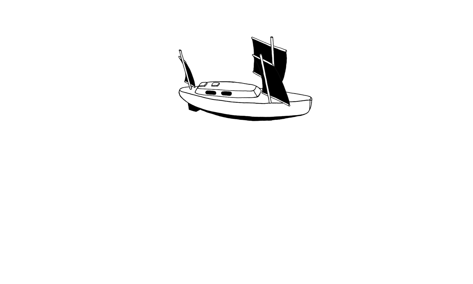
Below are some sail configurations. Click once ore twice to enlarge: First Beam reach to close hauled in light wind:

The same points of sailing in stronger winds

Downwind in light air.

In stronger wind the lugsail is converted to a squaresail by moving by using two halyards and two downhauls. the downhauls is attached to the stem making the sail lifting.

In stronger winds there is reef points. Now I lashe the sails to the spreader thus reducing the compression on the mast.

In really strong winds I use a square sail set flying thus awoiding spars up in the air.

To be continued…

Regards Yrvind.

BRONZE SOLES

The bronze soles are now sequrly in place . They are there to protect the bottom when the boat takes the ground and is being transported. They are ground plates for the lightning conductor. They do duty as ballast and they are antifouling.

It is good to have them in place but the job has taken longer than anticipated. To handle reality one is always simplifying it. Like a map if it shows to many details it just becomes confusing but this also means tha it is diffucult to estimated how much time is needed to finish the job. No problem with me I take the needed time to do a good job and I enjoy it. Building boats and sailing them in deep water that is what makes life worth living.

This time I made more mistakes than usual. By definition ballast is heavy. Each sole weighs 53 kilos or 117 pounds. When I was younger it was no problem to lift that wheight, not more than a girl and I could handle them alright. I can still lift 53 kilos. The problem now is that the next day I might get pain in my back. Freindly people in the building helped me to do the lifting but I did not want to take to much of their time and hurrid.

There are two ways of fitting the keel bolts, before or after placing the soles on the boat. If you put the soles on the boat first you do not have to worry about if the bolts are parallell to each other. On the other hand I had decided to embed the soles in elastic NM-epoxi and the epoxi has to come on before the soles and once you add the hardener the clock starts to tick therefore you want everything to go in a hurry. Parallell keel bolts it had to be.

The holes in the soles for the bolts had to be drilled on a co-ordinate table. The travel of my co-ordinate table is 50 cm but the soles are 120 cm long. To overcome that problem I screved them on a 5 cm thick particle board. that way I could slide them on the co-ordinate table and extend its range, just. As a man was waiting for me I was in a hurry and mist one out of six holes. It took longer. I got even more confused and missed a marking on the second on now the hole came just at the bulkhead. Bad luck would have it so that the pilot drill missed the reenforcement and was bent and stuck in the hull. I tried every trick. I even whent and bougt an LPG-burner and heated the drill intill it was red hot. It was a 3.5 millimeter long thin drill and the heat did not penetrate the 50 mm thick solid glassfibre. After a while it broke. Finally I succeded in drilling it out. Now I had six holes in the wrong place. I had to lift of the bronze and plug the holes. Put the bronze back and drill new holes in the correct position. The thing is not to lose patiens and the good mood.

I did not sin by making  errors. Sin is to continue to walk on a road that leads astray. Once I find myself on the wrong way I must turn back and find the good road. Then everything is forgiven. Because I realise that if I quickly and consistently discover and correct errors then in the end I will have a good boat I do not lose patience but correct mistakes.

Below follows some pictures. Click once or twice to enlarge.

Abowe. The sole on the co-ordinate table. The particle board that made me able to slide it so that I could get all the holes parallell can be seen.

Abowe tapping the holes using 3/8 UNC for the bolts. I had imported them from Topplicht in Germany.

Above. The position of the holes are marked. After that I remowed the core. Filled it with glassfibre flock and injected epoxi. A insex key on a powefull drill was used to get under the outside skin. Big forces was generated Divinycell H 100 is very though and strong. One six mm key bent like a cork-screw, 8 mm was strong enough.

Above: The core is remowed. Next stepp filling lassfibre flock with a pair of tweezers and injecting epoxy.

Above: By hanging the sole above the holes and lowering it parallell to the hull the bolt came into place nicely after a few tryes, dry runs.

Above: The keel bolts from the inside. They are that long because the elastic epoxy has a very high viscosity and the surface is very big. The sole has to be screwed down and aftertightend during several houers.

Above: The inside laminate is reenforced. Peel ply is used to get a good surface.

Abowe: The job is done and I can be proud. When turning the boat back on even keel I had to be careful. The center of gravity is now much lower and the boat had a tendency to flip over. If cought under the boat I might get badly hurt or even irreparably damaged. To avoid that a the rope below the boat is there to restrain the mowement.

Above: To spread the load I use 50 x 50 x 3 mm washers. I have not desinged this system to be sufficciently strong but for maximum strenght. Thats the way I like it. You never know when the unexpected arrivies. Then I am prepared. It makes for good sleaping to know that you have done everything and you also feel proud.

To be continued…

Regards Yrvind.

LET ME EXPLAIN.

About boats and feets. Moe Joe has misunderstood me. It is not a good idea to put in a 5 feet middle piece in my present boat to convert her to my next. Not for me. I always like to start with a clean white paper. But it is true sometime boats are successfully made bigger by putting in a middle piece, but that is mostly for cargo carrying boats.

Thing is I do not want a bigger boat. In fact I am consider a smaller one after this voyage is done. Why this present ten-footer is so big is because it is so slow and has to go such a long distance and has to stay at sea such a long time. Among other things I hope to show that measure boats by length is a bad idea.

It is not only ridiculous to have a ten feet role. It is ridicules in general to measure boats by length. Boats are three-dimensional objects in the real world objects have volume and weight. Only if such objects are similar shaped can one dimension be used as a measure, even then it will be not right because different properties scale differently like surfaces speed volume and stability.

There was once open a time a man selling whisky in all measures. A customer trying to be smart asked for one foot of whisky. The bright seller took a paper, wetted his finger in a bottle and draw a one-foot line on the paper, wrapped it up and handed it to the customer.

I like small boats. I am not going to get a bigger boat but I am going to get a smaller one, however it is going to be longer and narrower. The exact size of the next boat is not yet worked out. That is going to be one of the many pleasant occupations during the coming voyage. The designed displacement of the present boat is 1.5 tons. For the next I aim for less displacement, hopefully not more than 1.2 tons – I mean the total weight ready for an extended ocean passage of several months including me maybee a girl food and water and books. She certainly will be narrower and not so high. Captain Voss Tilikum has always inspired me. My next boat might be 8.4 meter long with a beam of 1.4 meter, a bit like some of the old whale-boats, but not a double ender. I like the advantages of doble rudders. Lenght in itself is not heavy or expensiv like one feet of whisky. My mind certainly will change many times before I make the final plans and start to build her.

If a shape is scaled up by 1.25 or more exact by the third root of 2 the volume doubles. For example comparing two similar shaped boats 4.75 meter and 6 meter, the 6 meter is twice as big.

Why do I build this ten feet boat if I think it is so ridicules? Answer it creates some very iteresting problems and nothing is as fun as solving problems. It also gives me a pensioner an opportunity to steer out to a better, cleaner, more natural world, a world were the talents I am born with comes to better use.

I like this world too, but the ocean – that is my habitat.

-:-

A dry run of the port bronze sole is now succesfully done. It has given me some trouble and taken time. The picture below is showing the keelbolts in place from the inside of the up-side-down turned boat.

The keel boalt are so long because when the bronze is put on top of the elastic NM-epoxi the 53 kilo weight is not enough to squise it out. the mating surfaces are to big. the six bolts will give enough force.

The core were the bolts penetrate the hull is replaced with solid glass reenforced epoxy. It is 5 cm thick, 2 inches. It dulls drillbits. Carbide tipped drills for composite use is expensive and I am thrifty -I like to spend my money vere they do the most good. I therefore bought cheapconcrete hammer drills, those used in the house building. I got a cheap ten dollar diamond file and rechaped the tips. Now it cuts like through butter. The file work only took 5 minutes. The below pictures are not very clear.

Abouve the drill before is started work on its tip.

Abouve the drill in the wise and the diamond files.

To be continued…

Regards Yrvind.

PREPARING THE BRONZE AND THOUGHTS ON RIGGING

I am preparing for attaching the bronze soles. The 12 silicon bronze bolts are done. The holes for the bolts are drilled and threads have been cut. The holes in the hull are drilled. The surronding divinycell core is replaced with glassfibre-reenforced epoxi. Now I am doing a dry run. I will embed the soles in NM elastic epoxy. A problem is once the hardener is added to the epoxy the clock starts ticking. For this operation I need some help. At this time of the year most people seams to be more interested in Christmas than in building boats. We will se when I get hold of a trusty freind.

Picture below show the soleclose to its position.

An other thing. The function of the spreader I consider putting between the masts is to help one mast to get help from his twin brother to take up side forces. If however both ends of the spreader are fixed like a branch of a tree growing into a tree next to it like they were Siamese twins the structure will be able to take up torsion forces. That way the structure will be much stronger also lengtwise. That thought intrigued me. Here is an experiment. By connecting the mast like a ladder one mast is able to take up nearly twice as much lenghtwise force as if freestanding.

That the rigging becomes nearly twice as strong is a good thing. What is not good is that it becomes more difficult to handle. It becomes a ladder. The ladder is 1.2 wide. That is not that bad. At the ancient time of ketches many persons did not connect the mast becouse they reasoned if one mast breakes it will drag the other with it. But if it like a bundle is tied together it becomes stronger and may not brake at all. Also two mast may break at the same time in a capsize.

There is still time to reflect. This boat is to teach me general solutions that I can use after this planned 600 day voyage when I am not restricted to a ridicules 10 feet rule.

Below is a pictures of the experiment. The person in the door has kindly been giving me a hand lifting the bronze.

A view from the side. As can be seen with the same load the freestanding mast bends nearly twice as much. The couppled masts bends nearly the same although the load is only on one. Torsion does a great job.

To be continued…

Regards Yrvind.

A COMPRESSOR

I have a new freind in my workshop. An Aerfast oilfree compressor. A boat builders workshop is neccesarily dusty so it is important to be able dust off workpieces. Epoxy hates oil, even a fingerprint can do damage in the wrong place. I hate noise I do not even have the radio on, but the new compressor is quit and fast. That makes me happy.

Regards Yrvind.

ILLUSTRATIONS

Olle Landsell, perhaps Swedens most famous nautical illustrator has done a numder of illustrations for the Swedish yachting magasin Segling. Here with their permission i show them.

Click once or twice on the pictures to enlarge them.

The above picture show the food, musli and sardines, my eating for 600 days. Also books, food for thoughts.

The above picture shows the arangements.

The sailplan and lateral area. The lateral area is the combined surfaces of the rudders and the centerboard.

Obviusly there are going to be many changes as I am building.

To illuminate I am adding a map of the 30000 nautical mile route.

To be continued…

Regards  Yrvind.

THE COMPLEXITY OF REAL LIFE ALWAYS GUARANTIES AN OTHER SOLUTION.

The complexity of real life always guaranties an other solution. Looking at my mock-up I realized that I could make a better rudder arrangement. Seeing Marströms catamarans with their connecting bars for seven years I took it for granted that twin rudders needed a connecting bar.

One is blinded by preconceptions and hidden assumptions. This is not the first time. For example 1968 I bought an old wreck, named her Duga intending to do as Captain Joshua Slocum converting her into a world cruiser.

Below: Duga as a wreck. She was built 1885 as an steam launch. Click once or twice to enlarge.

I sailed Duga to Rio de Janeiro Brazil 1969 – 70. She was later sold in Florida. I rigged her as an staysail schooner. To prevent her making leeway I gave her a daggerboard. She sailed well.

Later Duga in the Bahamas under US ownership

Duga had her rudder post inboard. I gave her wheel steering and placed the quadrant behind the rudderpost as I had seen on other boats.

1971 I started to build Bris. She was a double ender. I had been happy with the wheel steering. Problem was the rudderpost was now at the stern, the very aft part of the boat. The problem was easily solved by a stainless pipe construction for the wire blocks to give them required distance from the quadrant. I sailed her happy for many years

A map showing some of Bris passages. Later I sailed her to Newport RI where I donated her to the Museum of Yachting.

Bris in Mar del Plata Argentina with a girl freind. The stainless pipe construction holding the blocks for the steering arrangement can be seen. Click once or twice on the picture to enlarge.

Then one day many years later back in Sweden standing musingly looking at her I realized that I could have turned the quadrant 180 degrees and would not have needed the stainless pipe construction, that although had worked fine had been unnecessary and a worry in ports being fragile compared to the rest of the boat.

One is blinded by preconceptions and hidden assumptions.

Now as I was looking at my mock-up I realized that if I bent the tillers toward each other I did not need the telescopic connecting bar the universal joints and all that. The bending would put the tiller more to the center and I would get the needed distance between the quadrant and the steering blocks. The rudders would then move in parallel by holding two two leeward pulling lines together on one side and the two windward pulling lines together on the other side. When I liked to use the rudder as sea-anchor the steering ropes would let me be able to put them in V-position acting as brakes.

Pictures below. If you do not follow I have not expressed myself clear enough and more will follow.

Do I spend to much time solving problems? No – nothing is as much fun as solving problems. By evolution man is a survival machine. The Swedish lifestile means that the gouverment solves all your problems and in exchange you are a slave working to make the economy grow. The idea is that entertainment and comfort shall make you happy. Most people spend their life waiting for something. My planned voyage is a thing to hang up problem solving on. It creates a problem rich environment. That will help me to reach the higher spheres of happiness. The voyage has already started. Planning designing building and sailing is not to be seperated.

To be continued…

Regards Yrvind.

WAYS OF ATTACHING RUDDER-BLADE TO RUDDER-HEAD.

Although a deep-water sailor i prefer kick-up rudders. Flotsam and jetsam may damage a fixed rudder. Attaching the rudder-blade to the rudder-head should be given some thought. Traditionally it is sandwiched in a slot much like the blade of a folding knife. There are some disadvantages to this method. The blade cannot be lifted more than 90 degrees. That is good enough to sail in shallow water but in port it sticks out and is easily damaged by other craft. Then there is the question of play. If given to much play the steering becomes imprecise going downwind. If given to little the rudder jams in its slot. The most difficult material to use is wood because it swells and shrinks.

A more modern way pioneered by Bolger and others is to clamp  the pieces together using one bolt. At first it looks week but an analyze shows that it is strong. It is not equally strong on each tack but nearly so and strong enough. It is a simpler and lighter method and by adjusting the nut on the bolt you get just the right kind of play and friction. Also the rudder can be raised 180 degrees, an advantage in port. That is the method I use today.

The rudder mock-up now has kick-up rudder. the below picture show one rudder-blade attached in down position. Thanks to the platform I do not need ropes to raise the rudder-blade. It can be done by hand.

The picture below shows the rudder in up-position. Click once or twice to enlarge.

The picture below shows the same thing from the other side.

On wendsday I go to Gävle to give a talk to SXK -eggesundskretsen. I do hope the do not have a blizzard. Thursday I will be in Örebro to give a talk to Sweboat. Friday I be i Trollhättan to my dentist. There i will also visit my freind the ultra-distans runner Rune Larsson who gives me inspiration for endurance undertakings. Rune has won the Spartathlon three times. He has run across the US. He has rowed the Atlantic. He run 262.4 kilometer in 24 hours.

Rune and me running

Thanking Rune

To be continued…

Regards Yrvind.

RUDDERS ARE NOT WHEELS

Today I completed one more ½ scale rudder mock up. It was elucidating. When playing with it I noticed that the connecting bar kept the rudders parallel to each other only when they were aligned close to the boats centerline. At bigger angles the lee rudder turned more. At Marström I have seen plenty of M20 and M32:s Rudders mowing in parallel thanks to the connecting bar. Why did mine not do so? Simple, M20 and M32:s rudder axis are parallel. My rudder axes are not vertical. They are angled outward and back.

When you do something new you always get it wrong the first time. You are a child in a new world. Why, because real life is to complicate to be imagined. Even the combination of a small number of elements gives many possibilities. Six persons can be placed in 720 different ways around a table. With six people one can have a different setting around a table each day for two years. With 24 persons the combinations increase to six times ten to the power of twenty-three. This is remarkable because even if you change settings a thousand times a second you have to continue a thousand times longer than our universe has existed. A boat contains many more elements than twenty-four. That guaranties that there are always new possibilities – and new ways of making mistakes. That is why I spend much time on making mock-ups and why building this boat takes longer than building one a conventional one with drawings from a yacht designer. But of course it is so much more fun and instructive.

Going about one push the rudder to lee. With this rudder arrangement the lee rudder will turn more than the windward on. Does it matter? If it had been wheels on a car and you were concerned with the Ackermann steering geometry and all that – Yeas. But rudders are not wheels. The rudder force is proportional to area and angle of attack. Both rudders give turning moment. If they are not equally big I do not mind.

Why do I have a connecting bar? Answer – it gives a simpler line arrangement and both rudders turn at the same time.

Below are illustrating pictures.

Aligning the hinges with the help of a ruler.

The mock-up seen from behind.

Seen from above standing on my ladder.

Seen from abouve standing on the workbench.

To be continued…

Regards Yrvind.

BRONZE SHOE

THE BRONZE SHOES

The bronze shoes serve several functions.

They act as ground plates for the lightning conducting system. There is one sole directly below each mast, one at the port bilge and one at the starboard bilge.

I use a high tin alloy for strength. Being located between the bottom and the sides of the hull they protect the boat from chafe and make her bottom so strong that she can be dragged over concrete and rocks when handling her on land. Taking the ground will therefore be made with less worry.

The soles are mirror images of each other therefore I had to make two molds luckily I got their volumes very close the weight of the two soles differ by only 0.5 %. Their weights are 52.8 and 53.1 kilos respectively, totaling 105.9 kilos. They lower the center of gravity and acts as ballast. 12 % tin-bronze has a density of about 8.8. Lead with a density of 11.3 is heavier. Cast iron with a density of 7.2 is lighter.

Containing 88 % cupper they are antifouling a good thing when chafe wears away the bottom paint.

Bronze is the most expensive of these alternatives but its many other advantages made it a natural choice for me that always strive for perfection. However only comparing the price of bronze and lead would be wrong as there are many consumables and handling costs like making the patterns mold the work at the foundry and transport that would be the same. These soles will keep for thousands of years and may be an enigma to future archeologists.

Below are pictures. Click once or twice to enlarge.

To be continued…

Regards Yrvind.