RUDDER

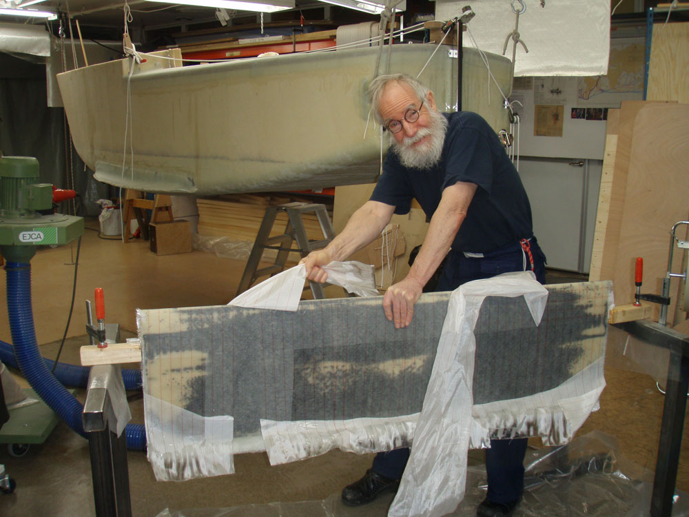
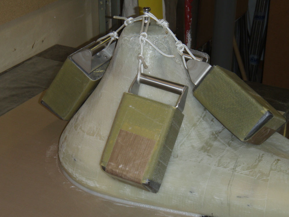
I like to have a big rudder to help prevent leeway. I also like to have it far back when surfing down the big waves in the roaring forties and screaming fifties. The when getting inshore I like to reduce my draft to and to be able to pull the boat up the beach. Finally the rudder is going to steer the boat while I sleep. I dont like selfsteering devices as the are complicated. I have good experiences with sheet to tiller system and also to get the boat to steer itself by its own balance. With sheet to tiller system a sheet is connected to the tiller to give feedback. In my design I do not have a tiller instead stearing lines are directly connected to hornlike extensions on the rudder and rudderblade as the below pictures will show. A threaded rod keeps them together. It is however very important that the rod is perpendicular to the surfaces wich must be very flat. This is how I have done it:
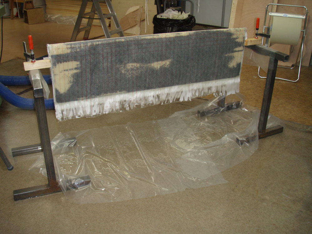
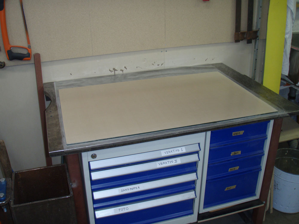
I covered a glass plate with teflon.

Click on the pictures to make them bigger

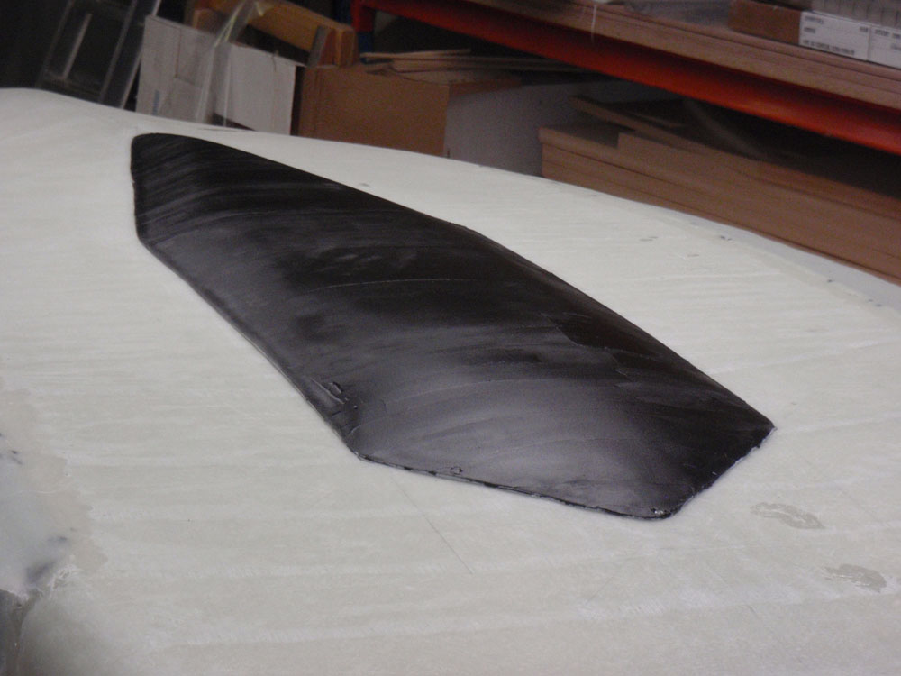
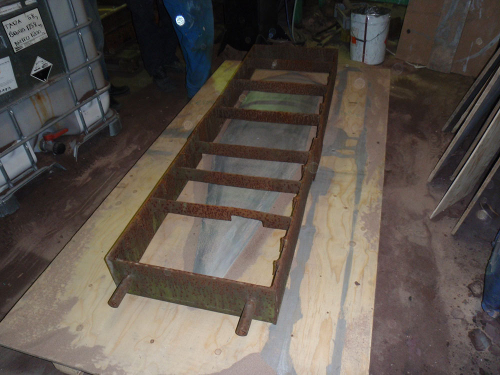
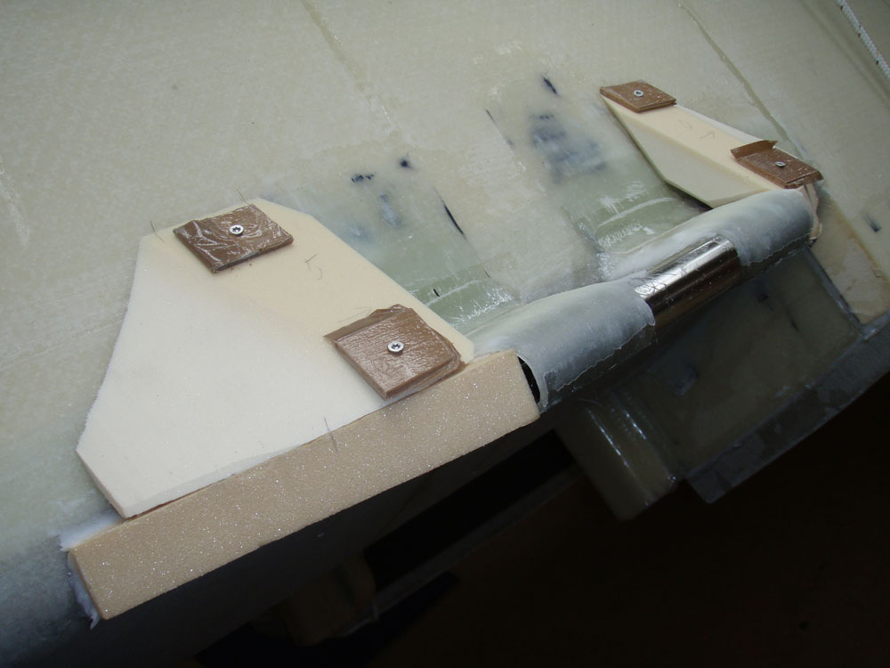
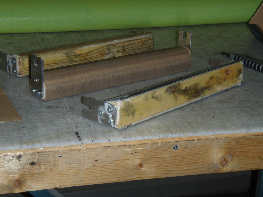
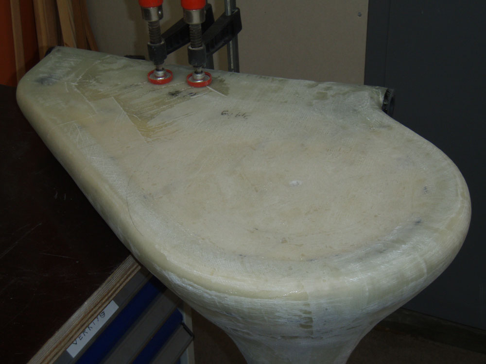
This is the surface of the rudderhead I vanted to be flat

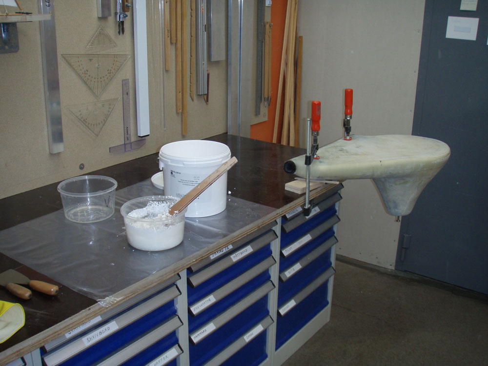
I mix NM-epoxy with filler

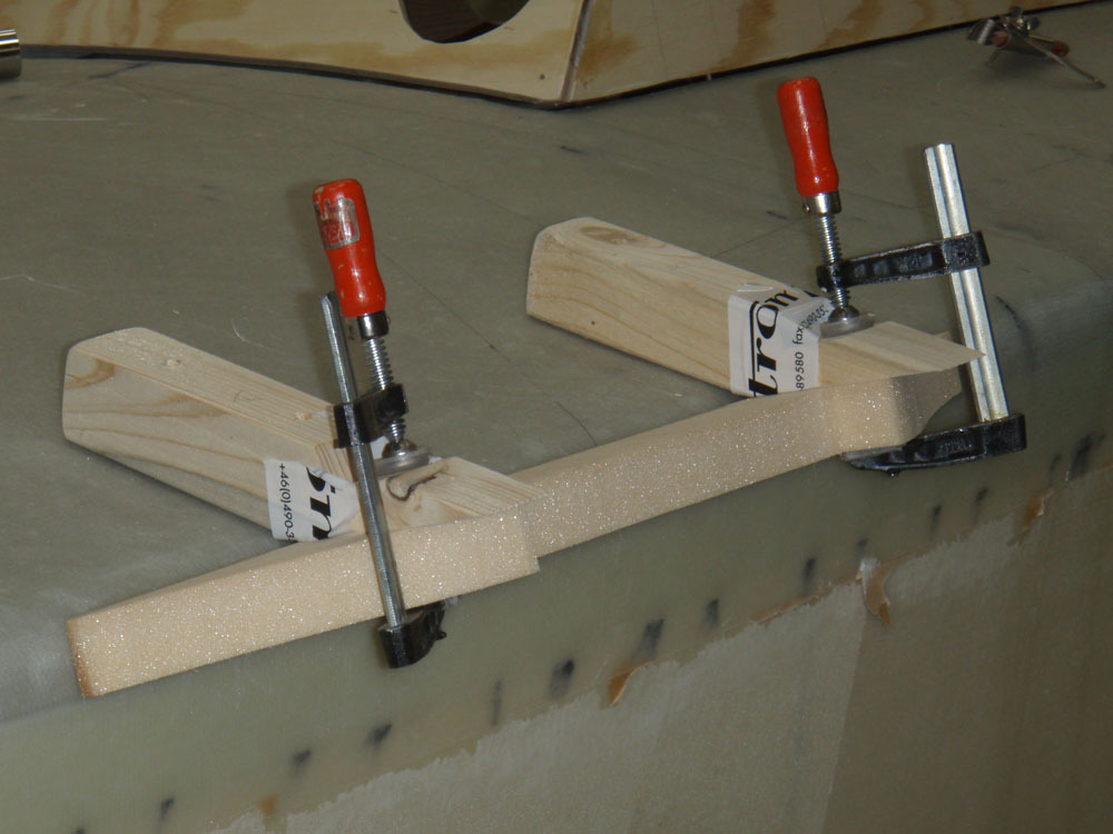
I spread the mixture on the rudderhead

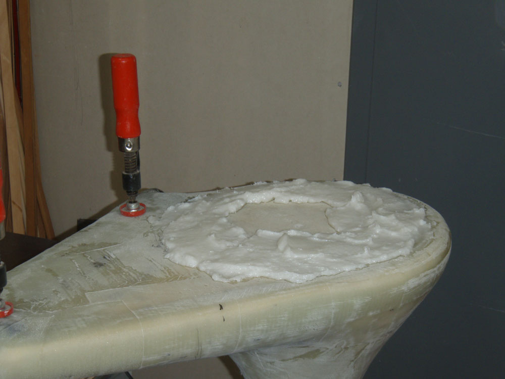
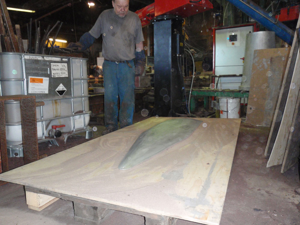
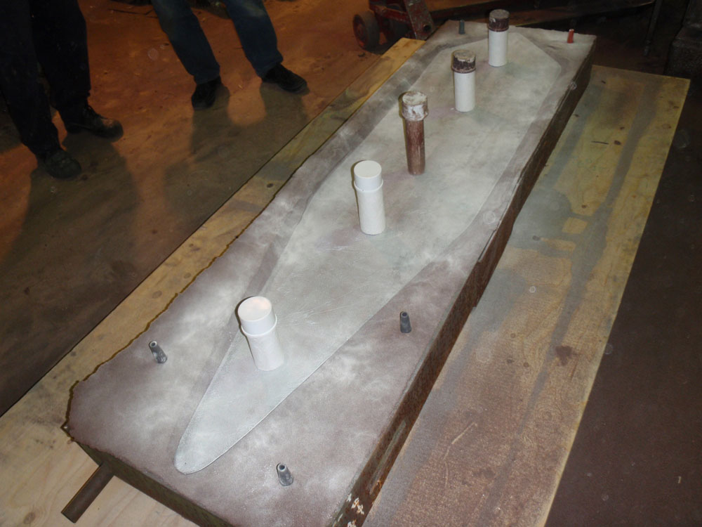
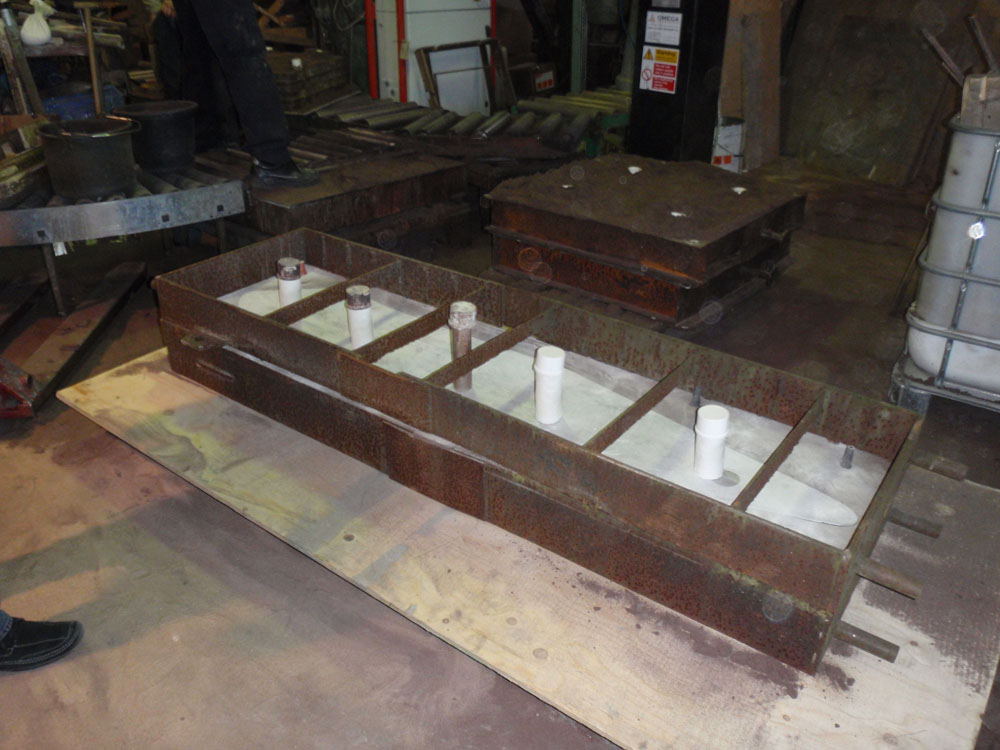
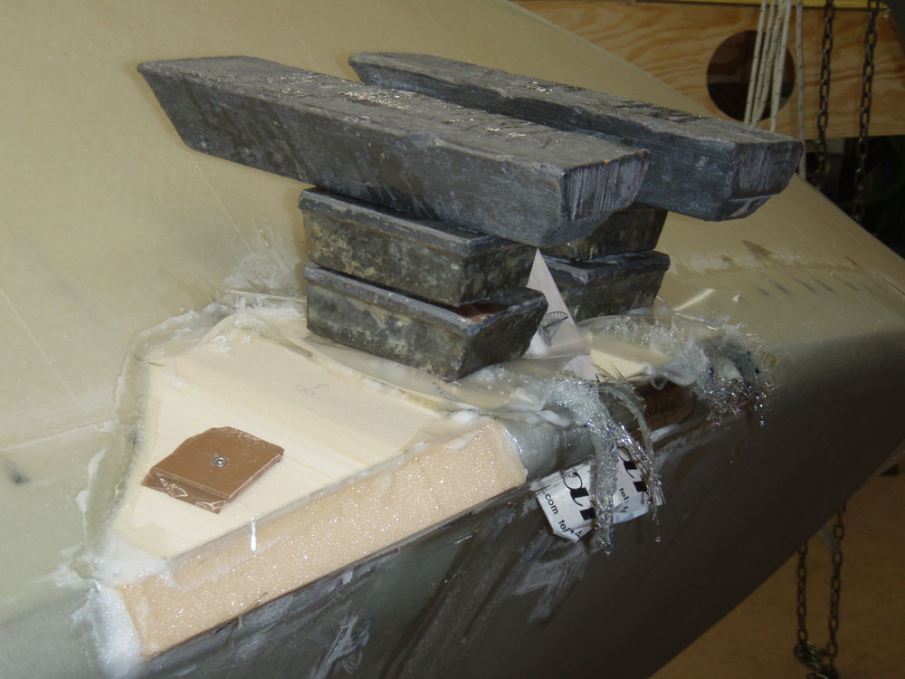
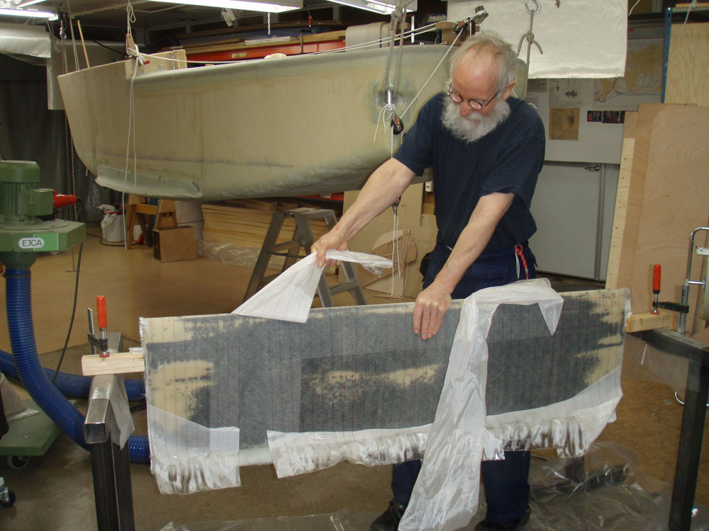
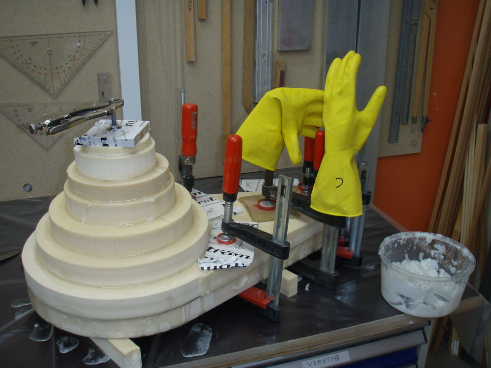
I put the rudderhead on the tefloncovered glassplate. I put on a lot of leadweights to squise out the mixture. After the rudderhead I repeated it on the rudderblade.

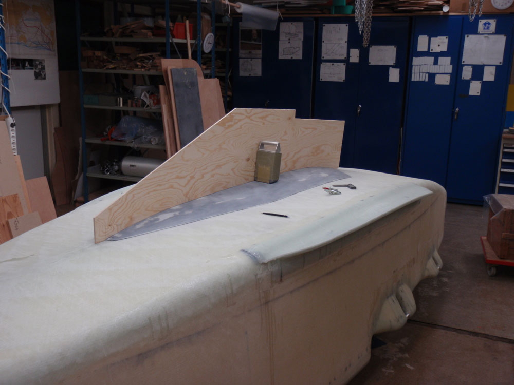
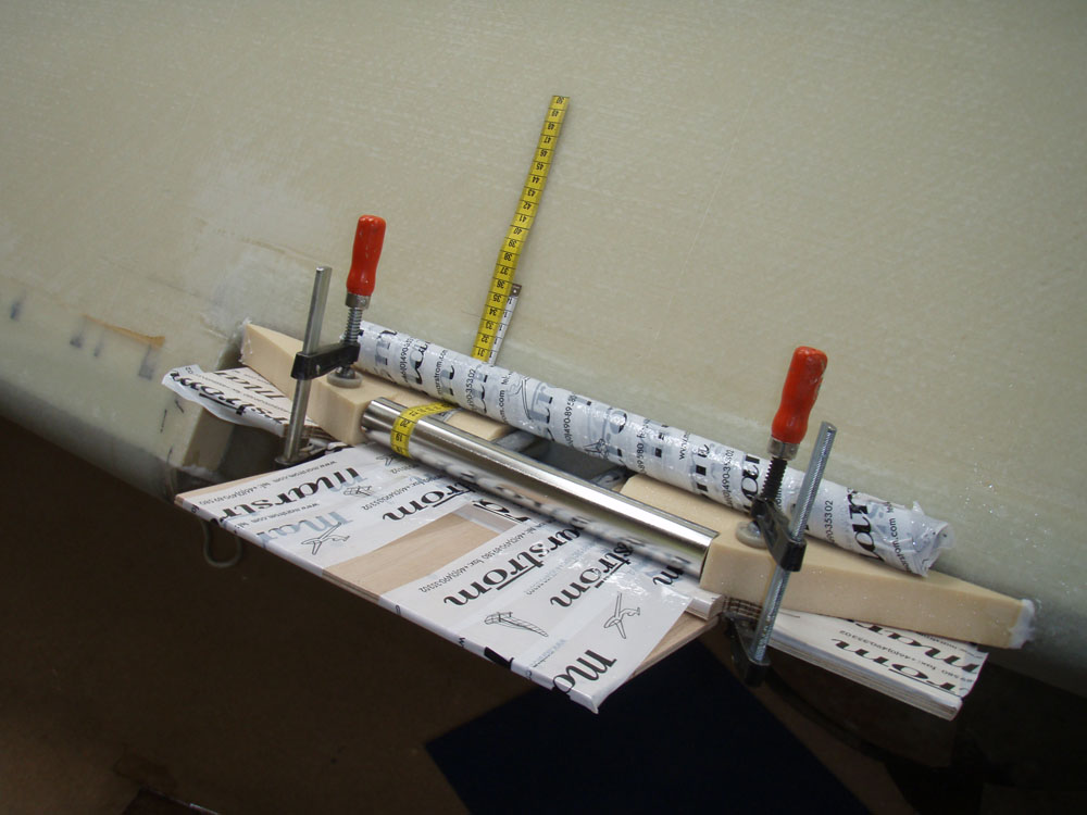
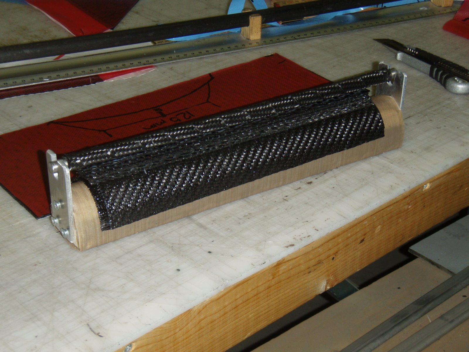
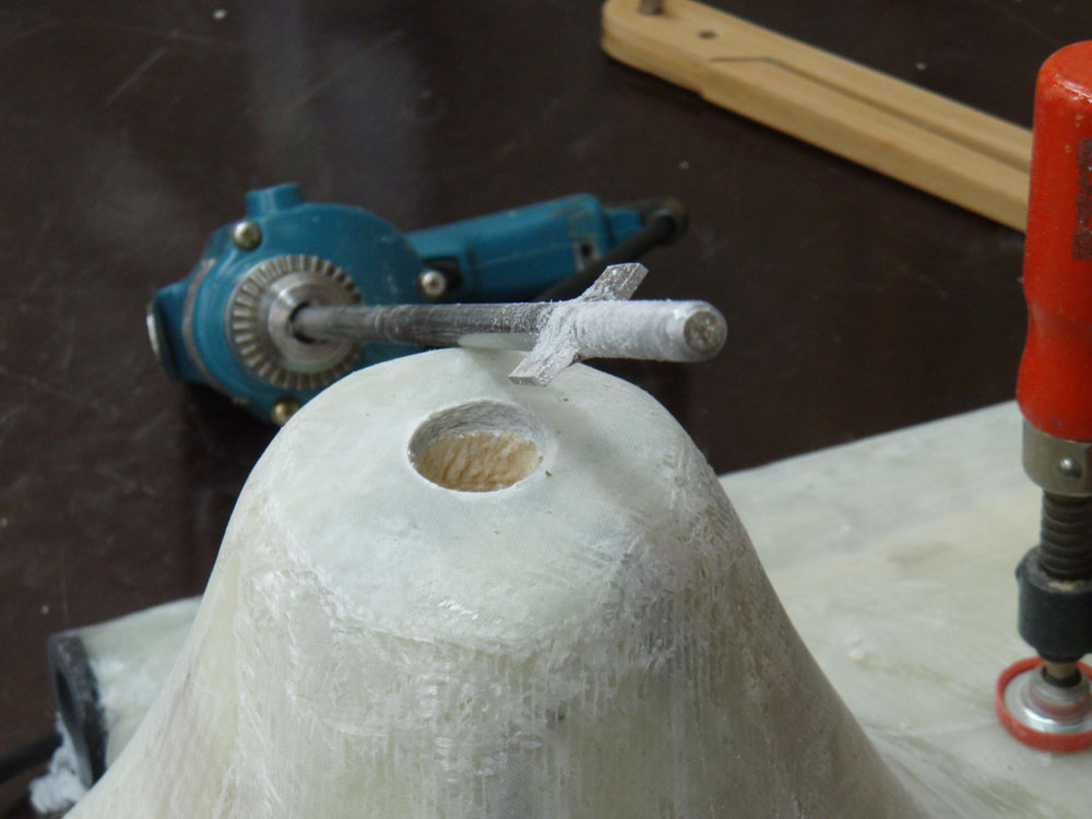
I made a 300 millimeter long 30 mm diameter drillbit and drilled a whole as perpendicular I could.

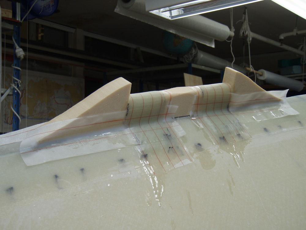
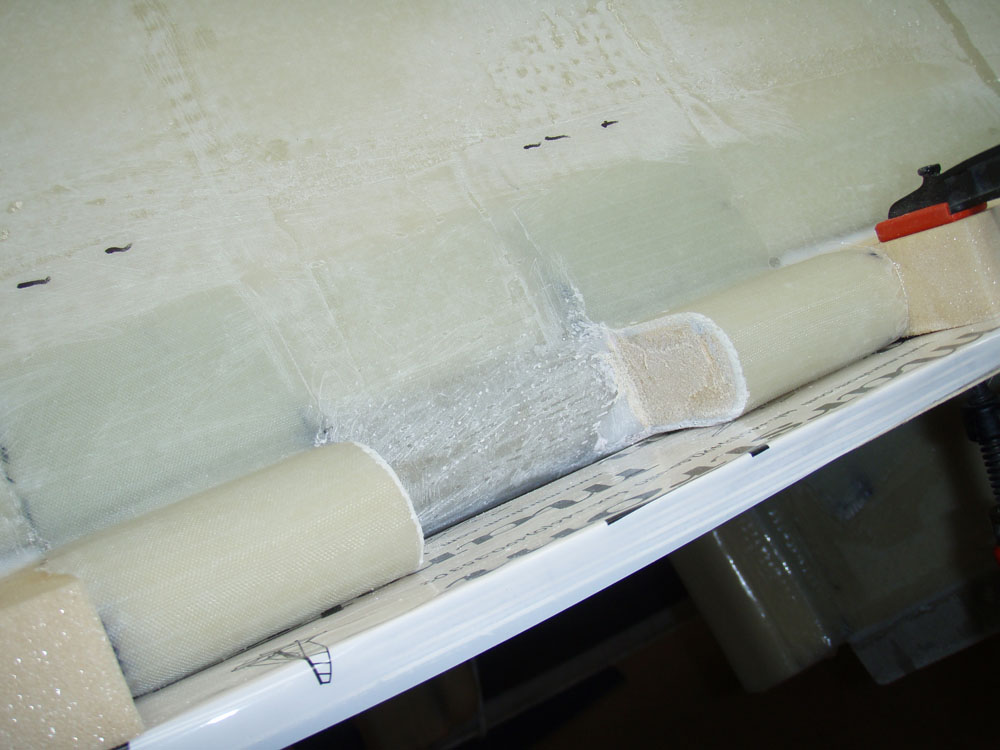
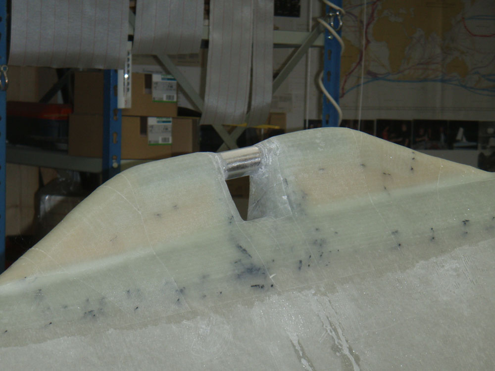
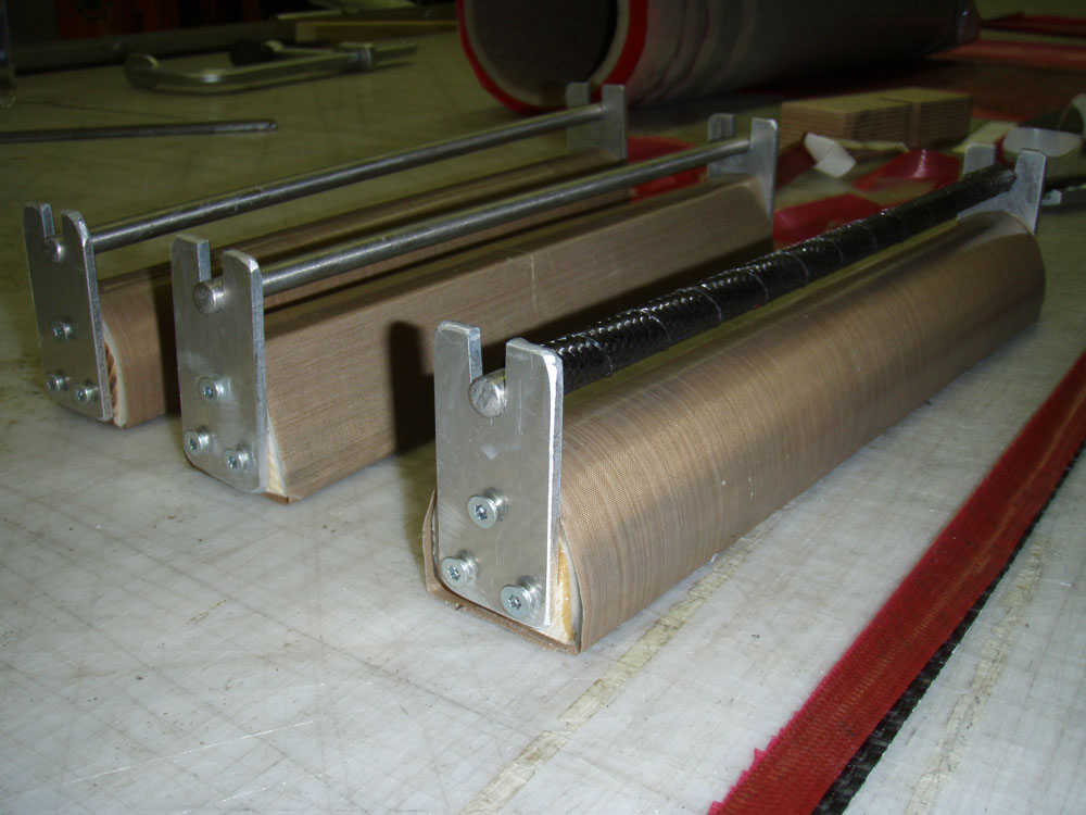
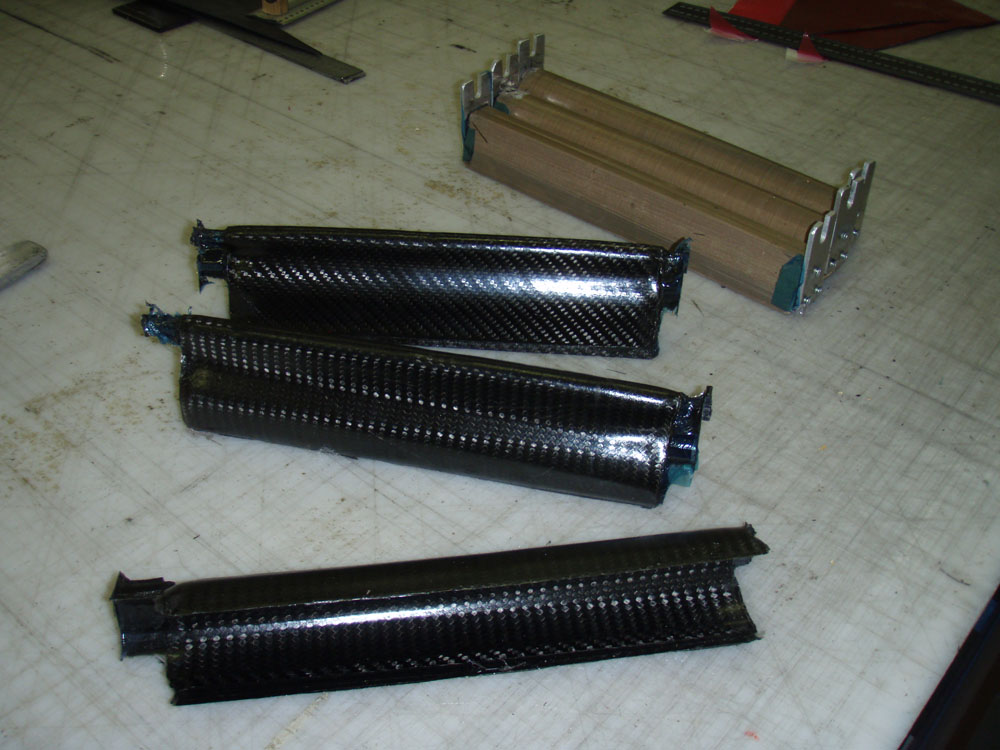
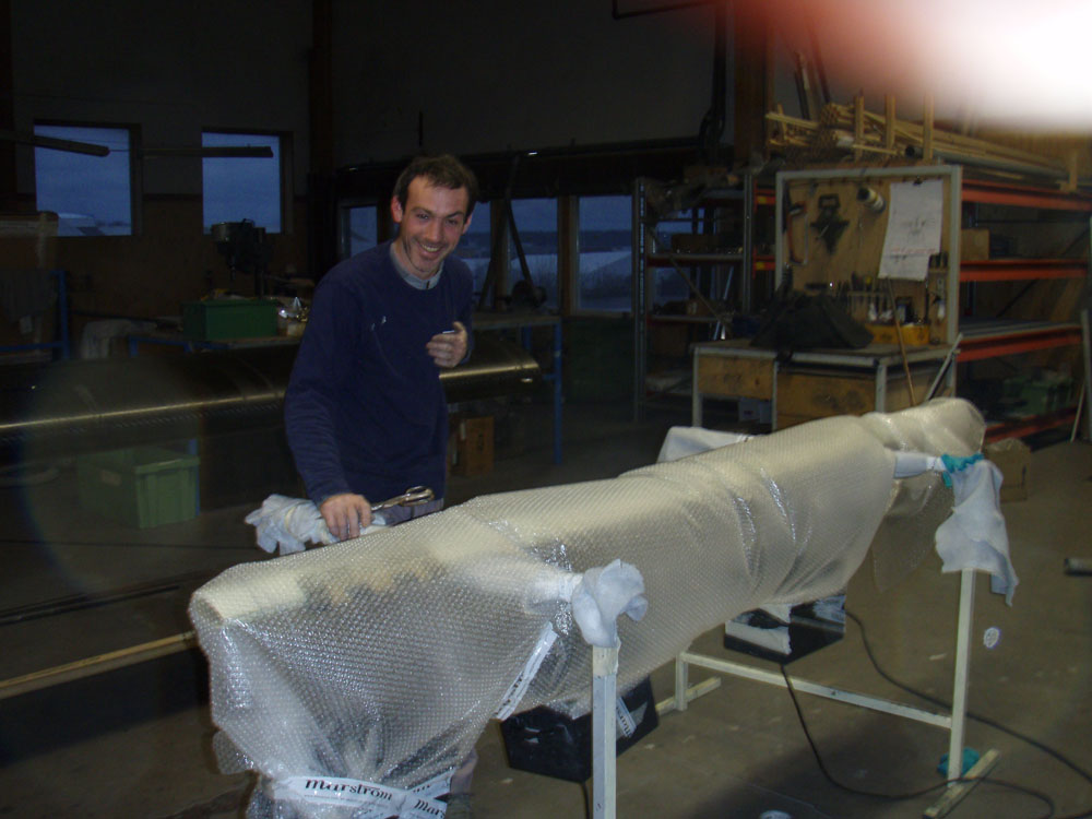
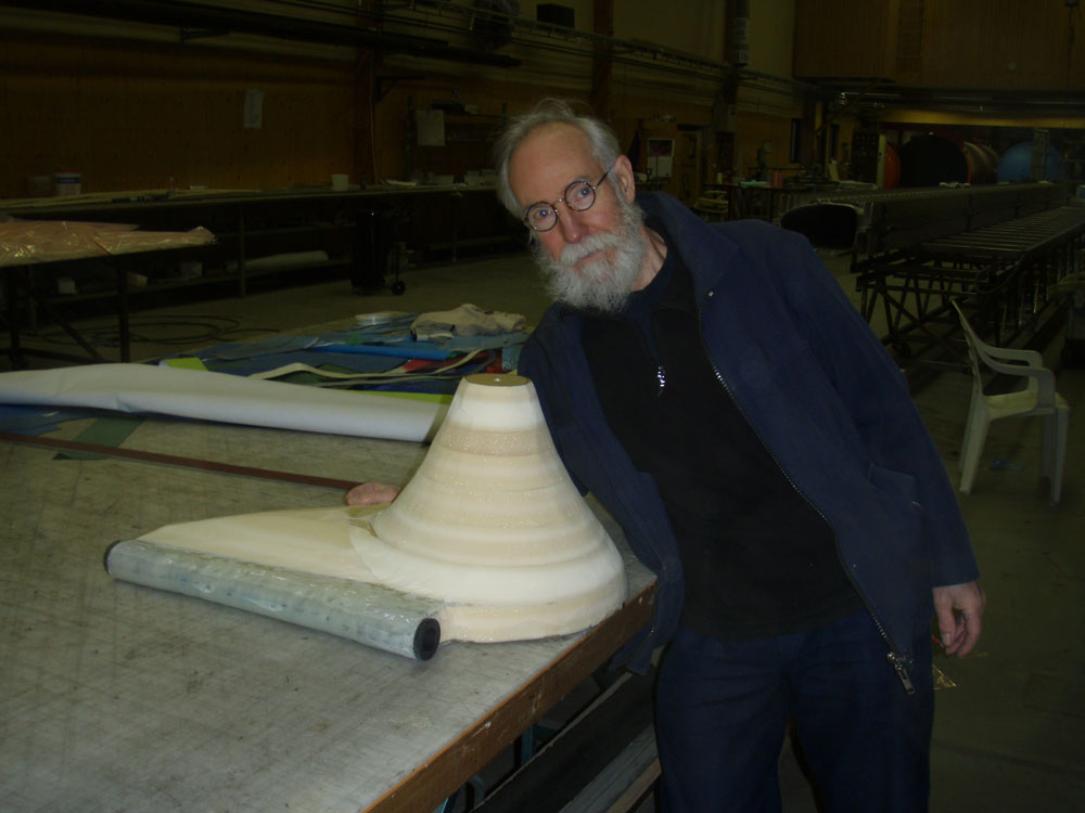
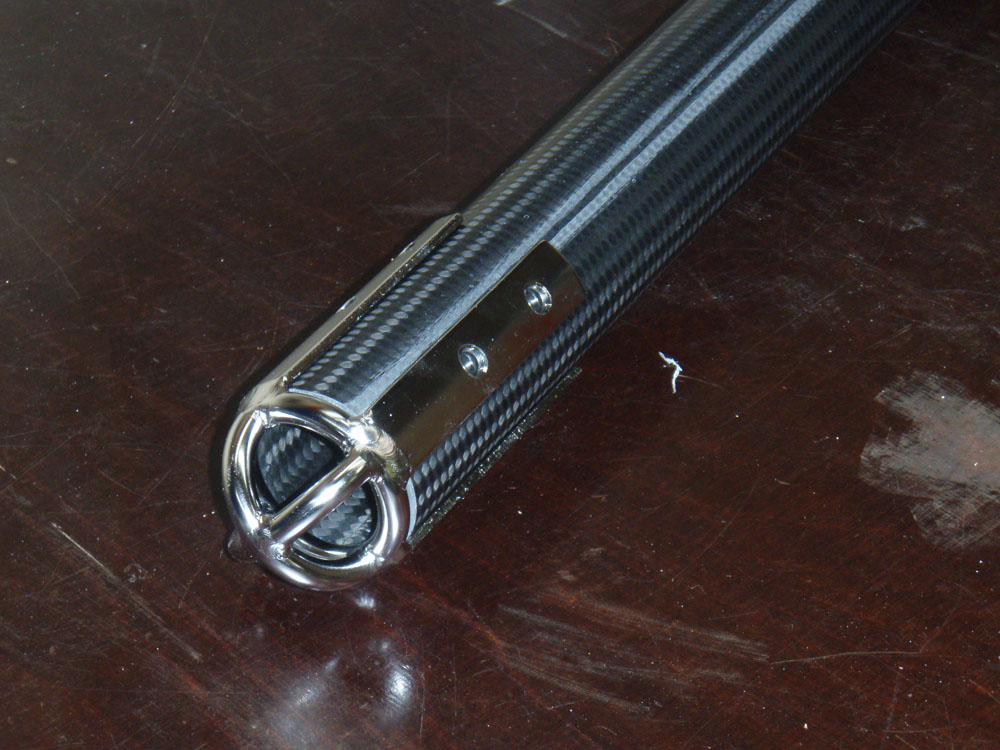
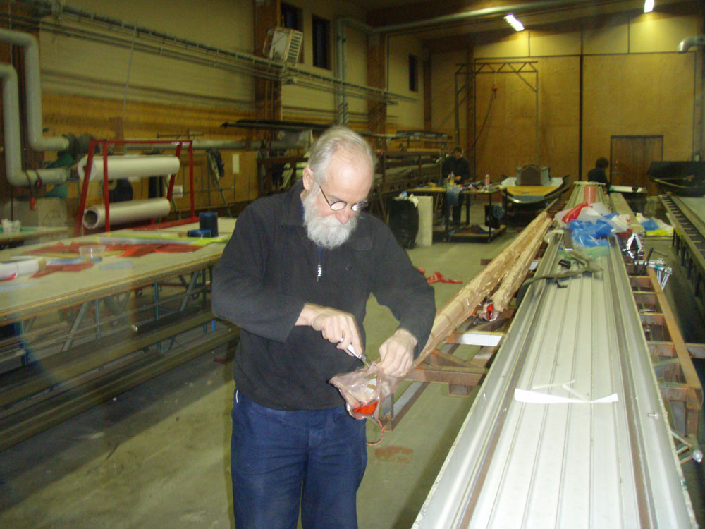
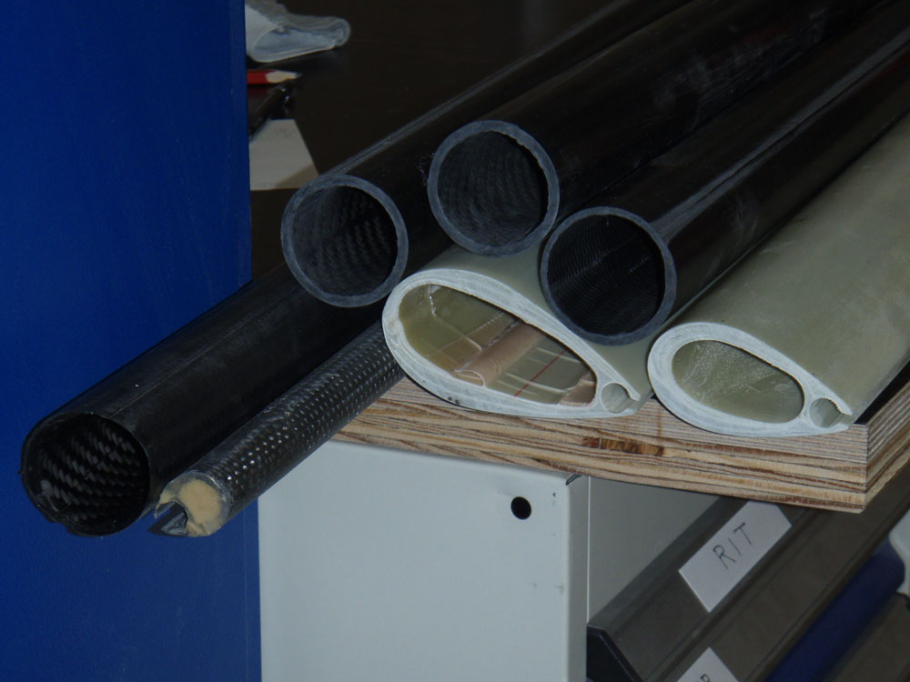
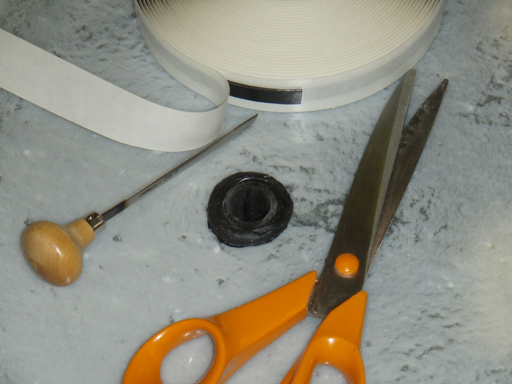
I had made a carbonfiber pipe to put inside the oversize hole. I closed the bottom part of the pipe with butylrubber.

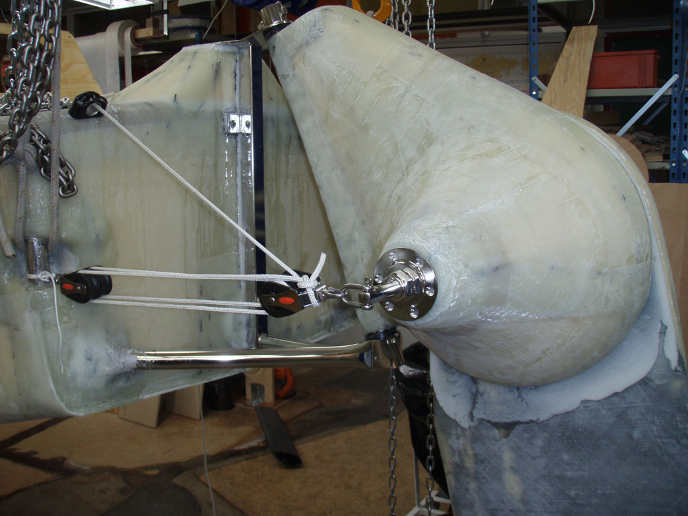
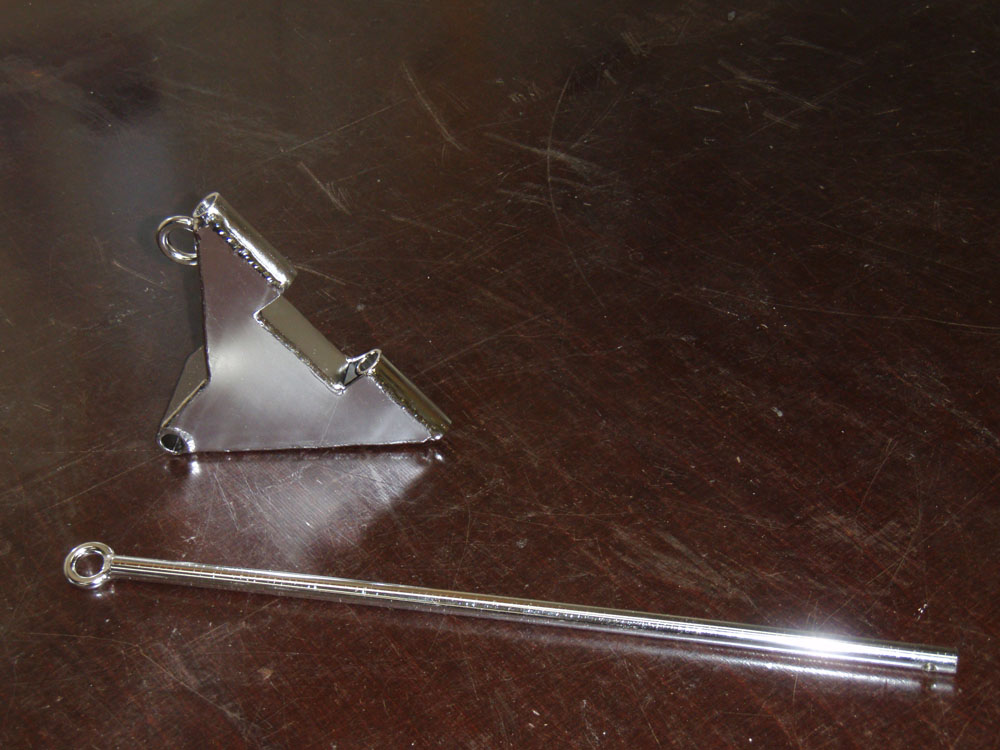
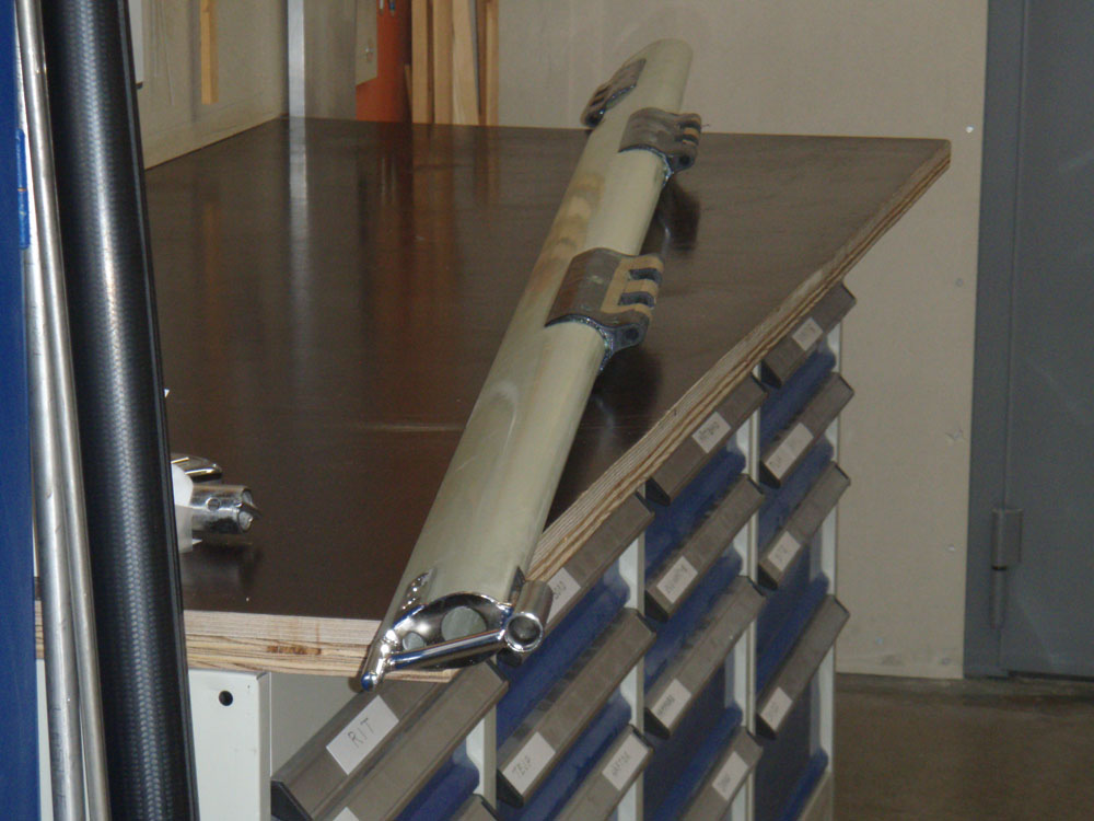
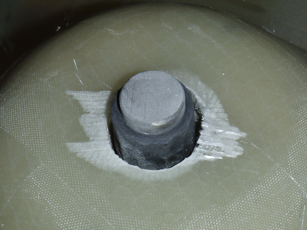
I had made a guide by welding a rod to steelplate and turning the plate in a lathe thus assuring a 90 degree angle. I turned the rudderhead 180 degrees. I put in the rod of the guide in the pipe thus making being 90 degrees to the surface. What you see in the picture below is rod coming up inside the carbonpipe. In the space between it and the oversize hole I poor epoxy to fix it.

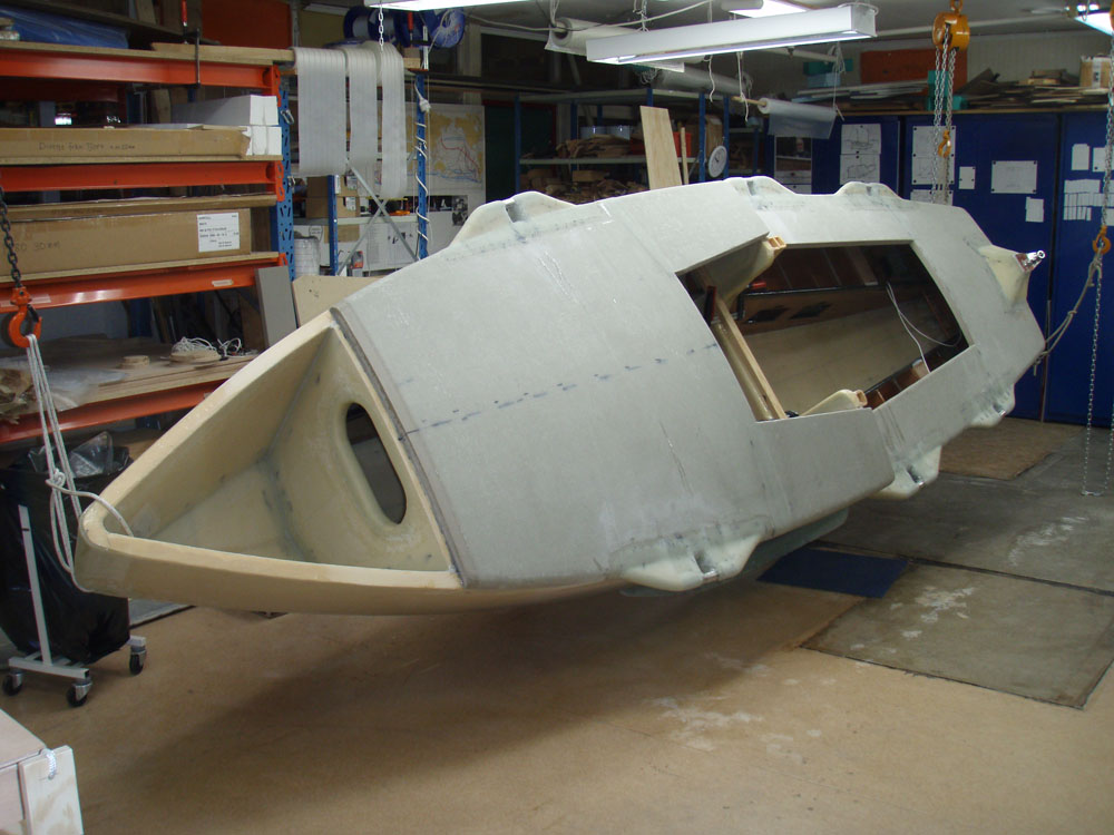
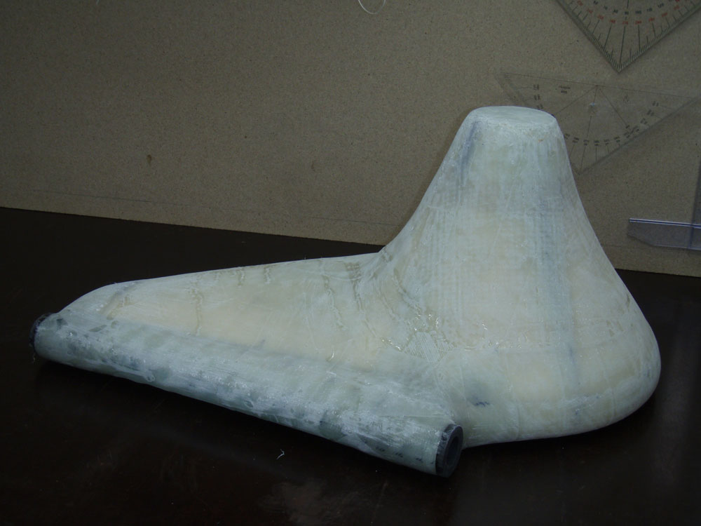
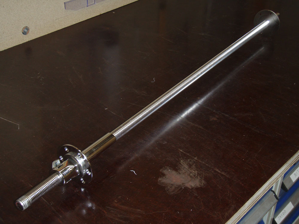
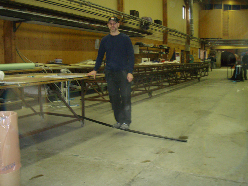
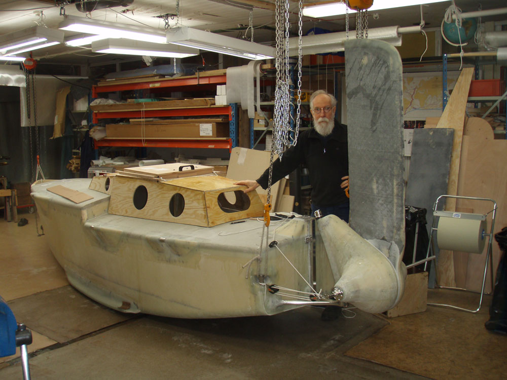
Everything worked out. Here is the rudder in the upplifted position. Thanks to the possibility to tilt up the rudder 180 degrees it does not stick out behind the boat were it can be damaged in port.

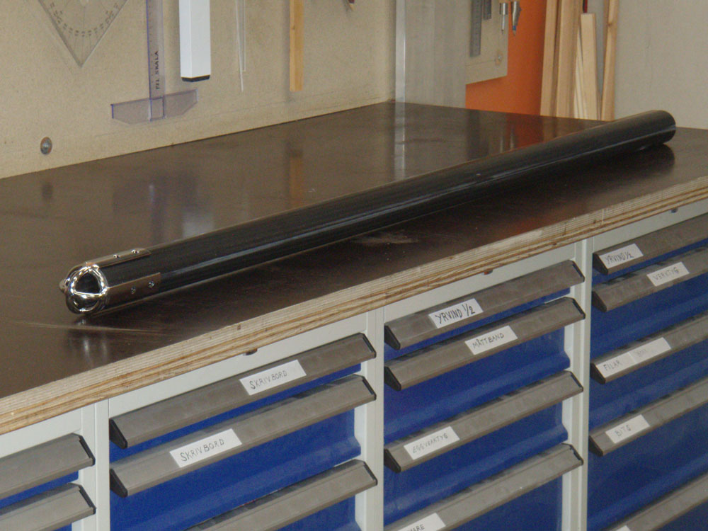
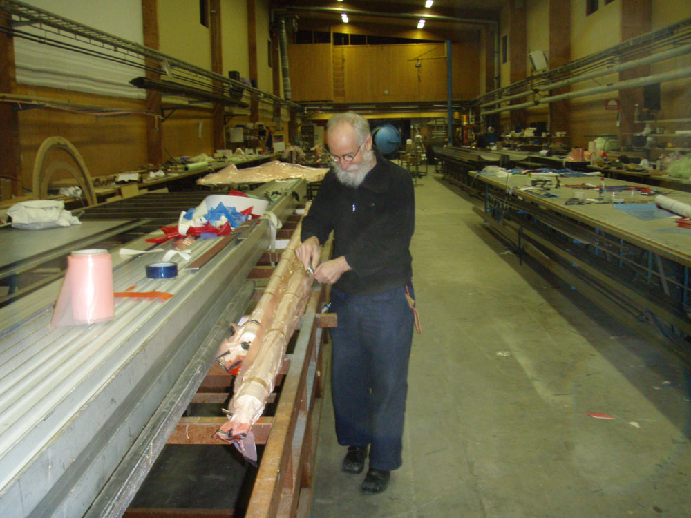
Here is the rudder in the down position.

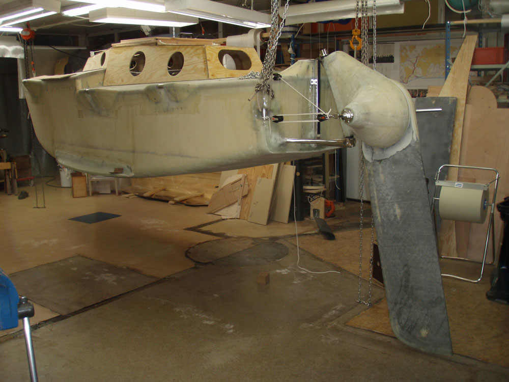
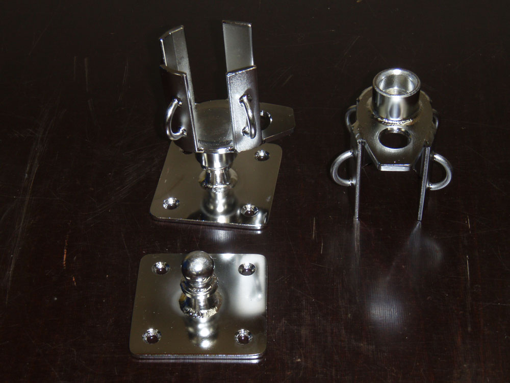
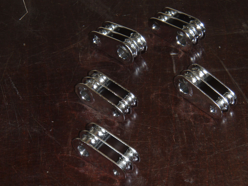
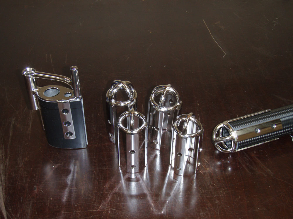
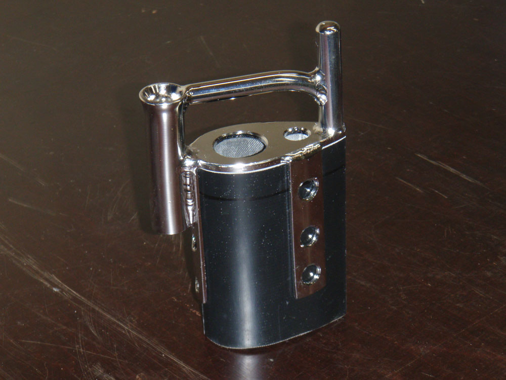
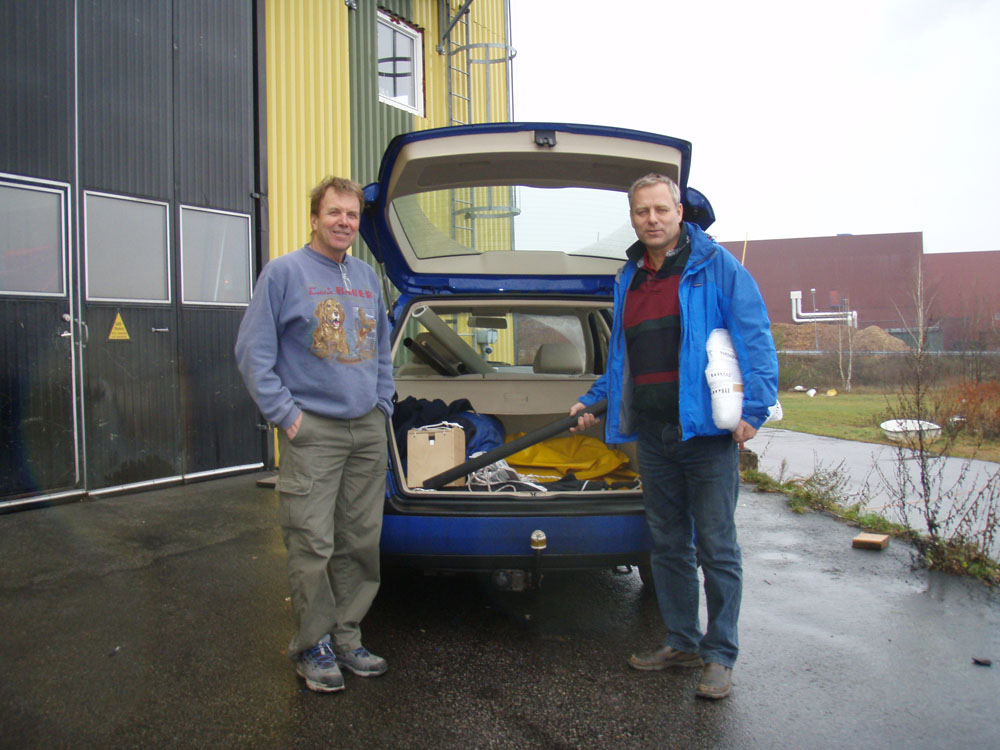
Here is the tackle I will steer with.

THE BRONZE KEEL

After much hesitation I decided to increase the draft of Yrvind by 3.2 centimeter 1 1/4 inch and reduce her load carrying capacity by 120 kilos. I would gain better stability. Watching grib weather files for Cape Horn daily for over a year has made me worried about its storm. Also I would get a very strong antifouling bottom if I made the keel of bronze. Here I would like to thank Carol of the Copper Development Association very much for paitiently ansver my many silly questions.
The foundry BLOMSTERMÅLA METALLGJUTERI did now as with the leadweights an excellent job. To celebrate I will give talk at TIMMERNABBEN YACHT CLUB tuesday 7 of April 1900 welcome.

Below are some pictures. I started to make a pattern. I used square cut divinycell and glassfibre and NM-epoxy to make a pattern Martin gave me advice. Thank You.

As the pattern was long and flexible I made a pattern for the pattern of plywood to check it in the foundry.

First we put the pattern on a flat surface backed by sand.

Then we put the bottle arond her.

Next we packed her with moulding sand.

Next comes feeders and raisers.

More foundry sand is packed.

The mould is split the pattern removed and the surfaceces are blackend with graphit. The solvent is burnt of.

The bronze is melted.

Then poured.

The whole thing has to cool for several hours.

Then still pretty hot it is taken apart.

Now I can see one surface of my keel. It is still very hot but its starting to snow so it cools it quicker. Still I have to go for lunch before its cool enough to handle.

It weighs 126 kilos pretty close to my estimated 120. It has also shrunk 1 1/2 % But that is no problem. After cutting of the feeders and raisers I put the keel in my car and I drive one and a half houer north to Västervik where I unload her.

Next I start to get a smouth surface on her. She now looks nice and I am proud of my decision to make a bronze keel. To be continued.

A FUNNY THING ABOUT TIME

Last summer 22 April my 70 year birthday seamed so far away. Now its only one month away. My original plan was to launch the boat at my birthday and have a party. Now I realize that that have to wait – it seams only the gods know when the boat will be ready. The party and the launching have to wait.

However anyone genuinely interested in small boats are welcome to Baumansgatan 4 here in Västervik on 22 of April between 16 and 18 hours and have a look at the work so far. There will be no cakes or drinks and I will not accept any birthday gifts, but I will talk and ansver questions and you can take a picture of the boat.

THE CHANNELS

Channels are in a nautical sense the ledges projecting from a sailing ships side to spread the shrouds and to keep them clear of the gunwales. Its an alteration of obsolete chain wale. It seems that channels in the nautical sense are now also obsolete. Time is passing. I use them however, because I hope to be able to lean my mast 30 degrees side vise. That will achieve a few things like giving the boat more stability when the mast is to windward.

Theoretically, placing a lead weight on the mast top would increase stability even more.

In light wind the mast can be made to lean to lee stopping stopping the sails from flapping as gravity will keep them down.

Also more sail area can be projected to the wind and the sails will be lifting instead of pressing the boat down. Also bringing the sails to windward will give her lee helm. Keeping them to lee will give weather helm.

A tilting mast gives a sailor many possibilities to experiment with his rig.

However it has been a time consuming job with many different operations. I started by gluing a piece of Divinycell to the hull. I fixed it with wooden jigs.

(click on the pictures to make them bigger)

Then I put some glass fiber below were the metal fitting was going to be.

Then I put a shelf to fix the metalfitting

Here is the metal fitting and I measure how much unidirectional glass I will need. Al the glass work is done with NM-epoxy. The pipe (wrapped in Marström tape for release) is to hold down the UD-fibre.

Here is the result.

Now I am building up the shape with more Divinycell. Vertical athwartships pieces of glass is inserted between to make the structure rigid to avoid pealing.

Lead weights are employed to compact it and squeeze out any voids.

The final product have a lot of gluing surface and in theory should be good for twenty tons pull. A fair margin of safety even for Cape Horn.

Here are all six channels looking aft. I only really need the two forward ones but the other strong pints are good to have when experimenting with different sail sets and for lifting the boat. The aft one is for yuloh work. They give a place to put a foot athwartships and a place for the rope.

Here is a view from aft.

YRVINDS LATCH MECHANISM

Below part of the aft cabin with the latch system in the aft starboard corner of the hatch. (I only do one corner on the mock up)

Below close up of the latch system.

Below Hatch open, close up of coaming and the green spectra line and its holder. The good thing with this system is that it gives a lot of closing power, its fast and its out of the way with the hatch open. Nothing to snag and chafe. Coastwise cruising one may have to stand a long time in the hatch in heavy weather. Then when tired and weary, one thing one I can do without is a latch digging in to my flesh.

THE HATCH & MORE FITTINGS

Today Börje has been here with a load of good things. Here we are trying the toggle of the gooseneck on the mast.

Below the toggle and its pin.

Below the ball and the mastfoot. There is two sets as the forespare also has its ball and mastfoot.

Below is the dead eyes. The mast can be made to tilt to windward. The mechanism for that are dead eyes. Usually dead eyes has three holes. I use two holes and a spectra line. Just before coming about I release the windward shroud and the rig falls over to leeward in a controlled manner. With three holes in the dead eyes I feel there would be unnecessarily much line and friction.

While Börje have been working on the fittings I have been making a mock up of the hatch. Below is the inner coaming.

Below can be seen the gasket around the inner coaming, the flat pieces of the outer coaming, the rope guiding of the hatch with the hatch in its foreward position.

Below the hatch in closed position looking aft. There are two bends in the roof of the deck house. I will only keep the aft as the foreward bend makes the attachment point of the rope to high.

MOCK UP OF DECKHOUSE

There are many things to consider when designing a boat bound for Cape Horn with an old skipper who does not like to get wet and cold, but now finally I think I got most things right.

Through the windows in the aft cabin I will have a good view of the surrounding seascape from my comfortable chair.

From the bunk in my bedroom will have a good look at the sail.

There is ample place for ventilators and ducts of my waterproof system so that no water will enter even when the boat is upside down.

I have designed a hatch closing system on the principle of the Highfield lever. There is one latch out of the way below each of four corners of the hatch. From the latches a Spectra rope goes to a hook in the hatch which then can be made to press against a deep EPDM cell rubber gasket to the desired pressure and tightness. The good things with this system is that when the hatch is open there is nothing in the rim which chafes or snags.

Another advantages is that I can, in heavy weather have a modified kayak spray shirt permanently mounted on the hatch rim because the Spectra ropes can come through small waterproof holes is the spray shirt and I can from inside the spray shirt put the loops of the ropes on the hooks. I can therefore get inside the, to the boat attached spray shirt before before I open the hatch. In principle not one drop of water can enter the boat.

The mast is only 75 centimeter 2´6´´ in front of the hatch and therefore easily be reached without going on deck. The spar in the picture is a mock up of the mast.

The hatch is 40 x 45 centimeter a size I used on my first Bris in which I cruised many years. It is a size which suits me well.

I will be able to open the aft window in good weather to get better ventilation. It is closed tightened from the outside by bolts. Also the outside of the aft window is very easily reached from the hatch.
From the hatch I can also reach the water by leaning overboard. This is convenient when washing up and brushing my teeth.

I realize that my description may not be very clear but more pictures will follow as work progress.

THE DECK

Below is pictures of how I am putting in temporary frames to bend the deck to the right shape.

Now when the deck is done and I have to figure out the shape of the deckhouse

To be continued…

GOOSENECKS & OTHER FITTINGS

I decided to make the piece of the goose necks which is attached to the mast of carbon. I took a pieces from an broken mast and made molds of them. That they would not collapse under the tremendous pressure in the autoklav I filled them with wood. To get release I have covered them with Teflon.

A 10 mm rod is winded with carbon 45 degrees in both directions to make a hole for the axis.

Then carbon is laid on the mold, then on rod and mold.

Here the pieces are after having been cured in the autoklave.

Francois our Frenchman is helping me to glue them to the mast. He is so fast that it is difficult to get a picture of him. Finally I got my chance when he built a tent with three 2-kilo-watts space heaters to cure the glue.

Below is the mast with the three goose necks on it.

Below is the centerboard being laminated.

The next day I peel of the peel- ply. I do not have the strength of my youth.

I have to use all my force.

Here I have been shaping the attach point for the steering line on the rudder head.

Here it has been laminated

Below. In the meantime, Börje who makes Marströms stainless steel fitting have been kind enough to make some also for me.

Here is the axis which shall connect the rudder head and the rudder blade.

Below is the end fittings for the booms. In this case the heavy weather boom which also serves as a club at the end of a sprit boom to hold out a down wind sail opposite to the sprit sail.

Below close up

Below is the mast head fitting. It has several functions. The pin on the right side is to take a small rope lope. I do not have halyards but intend to push the sail up in its track so that the loop falls over the pin and then pull the sail down. To lower the sail I push it up again, then twist the mast. The intention is that now the loop on its way down misses the pin.

To the left is is a pipe which is going to take a pin from the top mast. It also serves as a point of attachment for the genua.

The bar between them is for me to hold on to when I climb the mast. It also serves as attachment point for back stays, running downwind. Running down wind I do not worry about wind resistance.

THE SPARS ARE DONE

Among a few thousand other things, Sam is a drummer in his spare time. Naturally he has built his own electronic drums of carbon fiber. Here he is jumping on the very light drum support pipe to show me how flexible carbon is. My mast of glass is twice as flexible as my other spars which are of carbon. Sailing south of Cape Horn among the icebergs there should not even be a doubt in my mind about the strength of my spars, not even during hurricane force winds. Everything is very strong and not very light. A carbon mast I am sure would have been strong enough at less than half the weight.

Here I am unpacking a spar just out of the autoklave, cutting up the vacumbag and removing the felt and peelply and release film.

Göran and Per, the owners of Marströms inspecting the spars which all fits inside my Volkswagen.
Per said: Thats a lot of spars.
Göran said: I would not call them spars.
Building a small cruising boat among the high performance multihulls I have to stand a lot of teasing.

Here I am home in my workshop regarding my treasure.

As can be seen I use quite rugged lay up.

During the workdays I have been to the Marström factory. During the week ends I work on the rudder and centerboard. Here is the rudder head. I am moulding the cone for the port stearing line. there will be another on the rudderblade for the starboard stearing line.

I have also been to Göteborg making money doing a lecture. At the same time I got a spare par of eye glasses. Also I was visiting the Garmin office discussing GPS and charts.
The work continues, there is a lot of goosenecks toggles, and other things to fit to the spars.