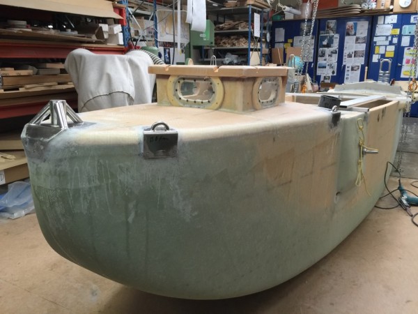
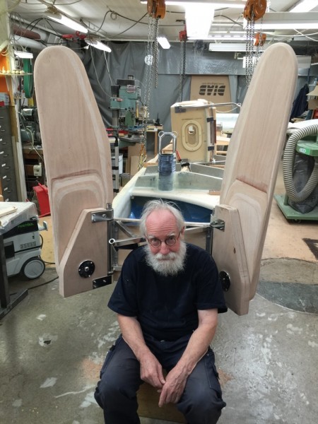
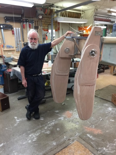
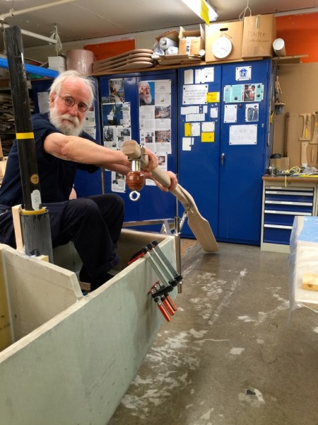
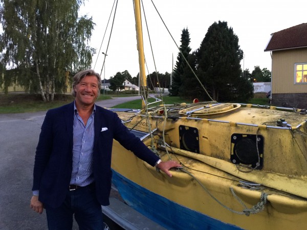
Fairleads for the stearing lines

Happy New Year from Yrvind.

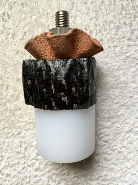
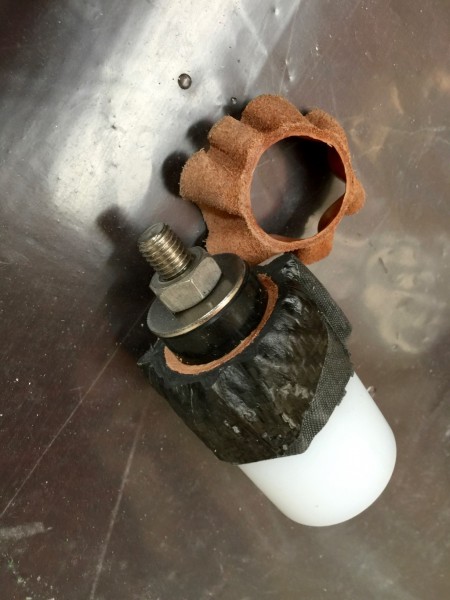
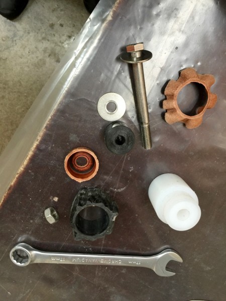
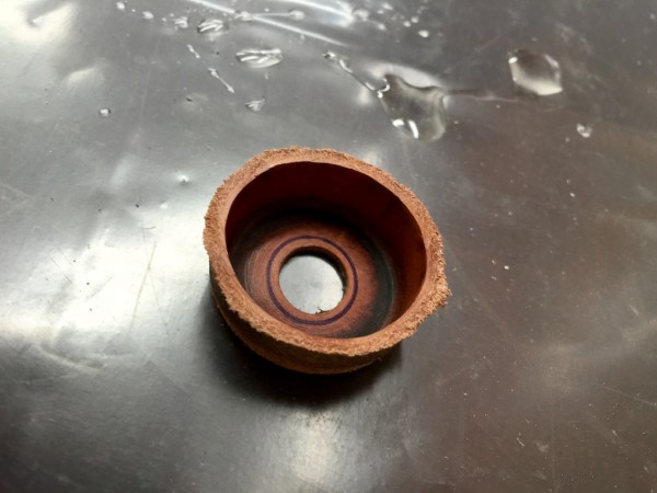
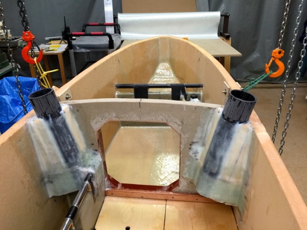
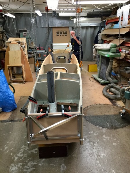
At present I am doing fairleads for the winch for the stearing lines.

There are two rudders. Each rudder have two stearing lines therefore four winches. Each winch needs two fairleads so eight fairleads.

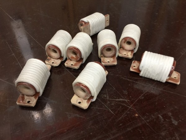
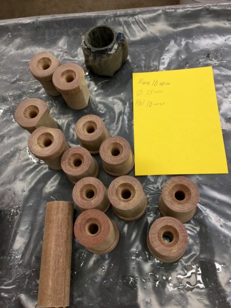
I am making them out of Tufnol rods. Tufnol is wery wear resistant, so are some other materials. The advantage of Tufnol is that it unlike many fat plastics glues very well with epoxy.

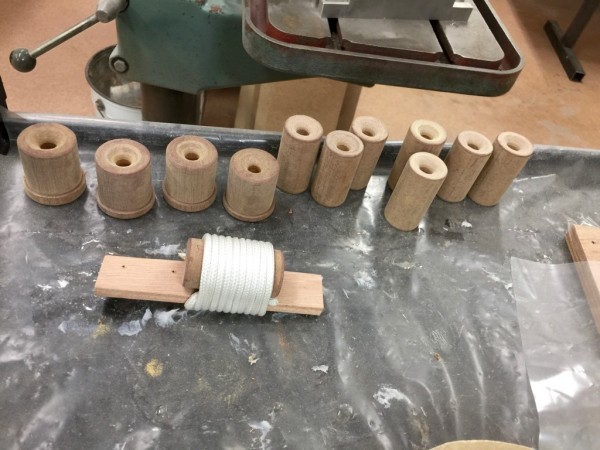
Below the fairleads coming from the lathe.

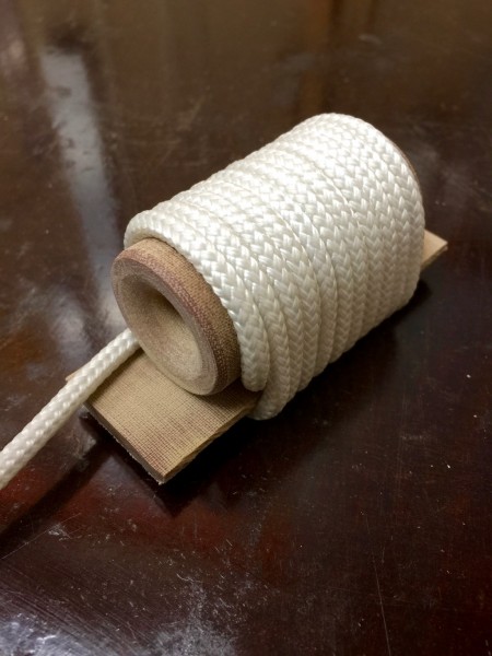
I attatch them to a piece of 5 mm Tufnol board with polyester string and NM-epoxi. The polyester string also takes epoxy well.

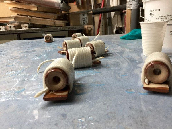
I soak them in epoxy.

After trimming and drilling screw holes products are ready. Next they will be scruved and glued in place.

Becouse its a hobby I do better work than I have to. Of course in stormy weather you feel snug and fine and proud to.

To be continued…

Regards Yrvind.

A WINCH TO ADJUST THE STEARING LINES

Not many people today sail without autopilot or windvane.

I do becouse its simple, cheap, takes up no space and is fun, also few things can go wrong.

A few things have to be kept in mind, no play in the system and a possibility to adjust the rudder angle rather precicesly.

On Bris I had a wheel and it was geared 10:1 to the rudder, that is ten turns of the wheel turned the rudder once. Adjustments of the spokes had to be done not more than a few millimeters at the time as the wind did change.

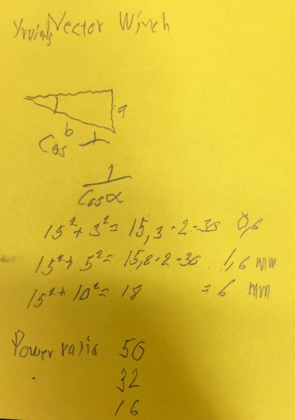
On Exlex there is no rudder. The stearing lines goes directly to the tillers. I realise i need a product to reduce line movement. The boat will move about in big waves. I have come up with the following device I call it a “Vector Winch”.

It works on the swig principle. The way you haul a line, especially a halyard, taut manually.

Theoretically it has a power range from infinity to minus 2.

For 30 cm between the fairleeds if you mowe the line 30 mm at right angle to the tension the line will be 0.6 millimeter shorter a reduction of 50 to 1.

50 mm shorten 1.6 millimeter reduction 32 to 1.

100 mm shortens line by 6 mm.

This way I can fine adjust my rudders.

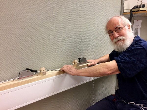
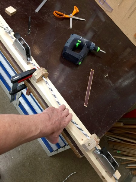
Photos below show a mock up. It works wery well.

There is 30 cm between the fairleeds and two line jammers.

Me happy with my device.

Tension the winch:

Below Photo from the side:

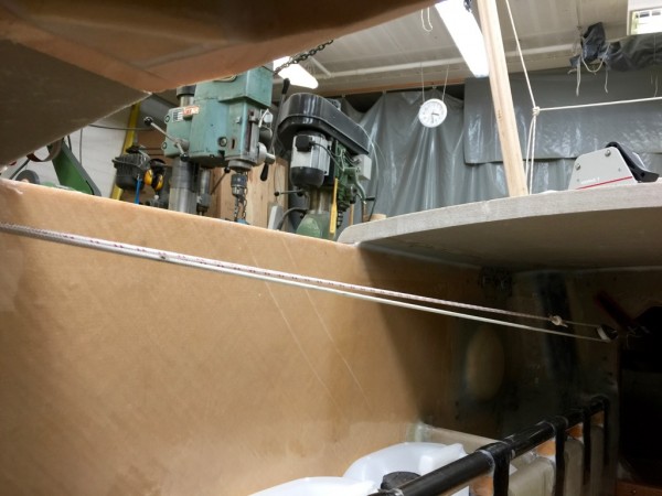
To use the device, release the jammer close to the tiller, tension rope the desired amount, close the jammer, release the secound jammer, take up the slack, close the secound jammer. Done.

These products will be mounted abouve my bunk where i spend most of my time reading sleaping drawing on the next boat “Boat Ideal”. When I am in other parts of the boat the jammers are released that way I can steer from every other part of the boat also.

To be continued…

Regards Yrvind.

PICTURES OF STEARING CONTROL FROM BUNK

Hello Friends. Here are some pictures from my work on the system to control stearing from the bunk.

I have no self stearing on my boats. I control the boat by adjusting tiller and sails. More often than not there is a windchange when I am in bunk.

Its therefore desireble to be able to control the rudder from there. At the same time I do not want water to enter the boat so there are leather seals on pistons in carbon pipes.

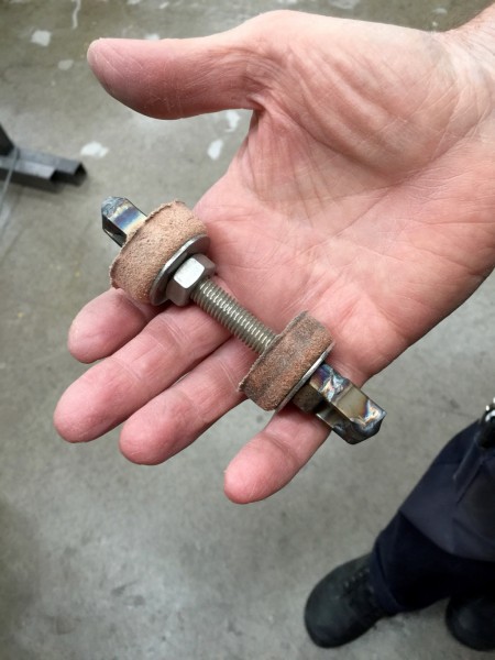
Below making the seals: The leather in the tool after being soakt in water for a day and dried to take the new shape.

Cutting her clean.

The tool dismantled

The product

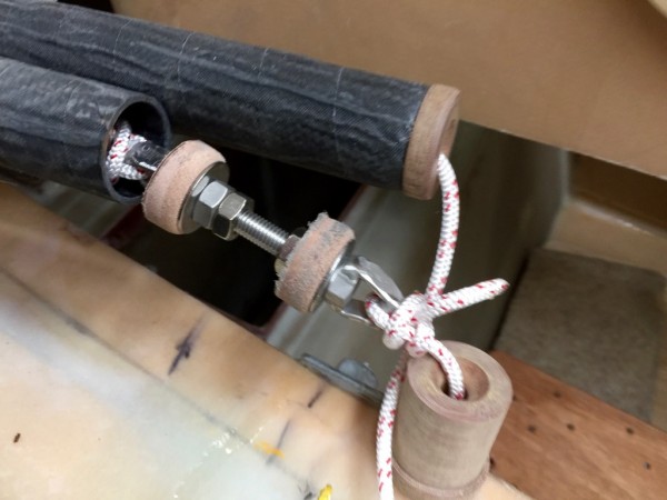
The seals on the piston. By dividing the rope there will be no wicking effect.

The ropes the piston ready to enter the pipe. The fairleads is also there.

The Fairleeds.

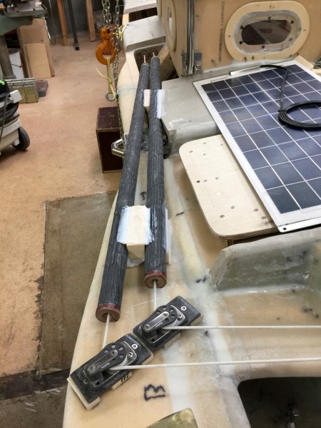
Lines coming into the boat

The lines in the bunk. Next step is to find the adjusting system.

Besides stearing the boat the two rudders will be used as a drouge and stabilising system when running downwind. By edging the two rudders a few degrees toe outhopefully I can make the boat go stright downwind in heavy weather.

To make it easier to work on the inside I will wait a bit by adding the full deck.

To be continued…

Regards Yrvind.

MAIN DECKHOUSE AND VENTILATION

The main deckhouse and ventilation is done.

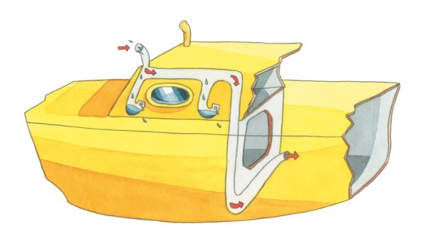
Below an illustration by Pierre Hervé.

In bad weather a mixture of air and water enters the ventilation cowl, like in a Dorade box the water is separated. In Exlex there is a water seal, like in the drain pipe under a sink. Thus all the air is ducted to the inside of the boat.  The Dorade box has a large volyme compared to the diameter of the cowl – if one can compare a surface to a volyme – should plenty of water come. As a back up there is a secound large volyme box.

The clean air now descends through a channel to the bottom of the boat, then crosses to the opposite side.

When the boat capsizes there is always some part of the ventilation system above the sea surface and as water cannot rise above its surface no water will enter the boat -same principle as in a centerboard case.

Some water that has entered the ventilation system may drain in the navigation cabin/ lunch room where it is harmless and will be taken care of by kajak pump.

There is a mirror image of the system on the other side. One side for incoming air the other for used outgoing. due to space restrictions I do like to have the crossings in the same plane therefore one system is crossing at the deck level the other at the bottom level. Therefore the two vertical channels are on the port side.

Below are some pictures.

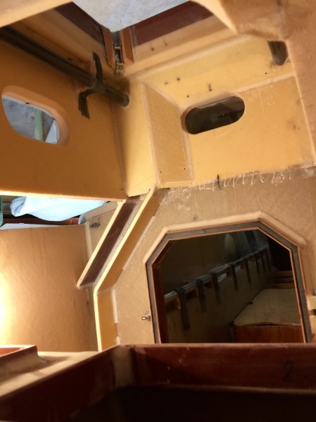
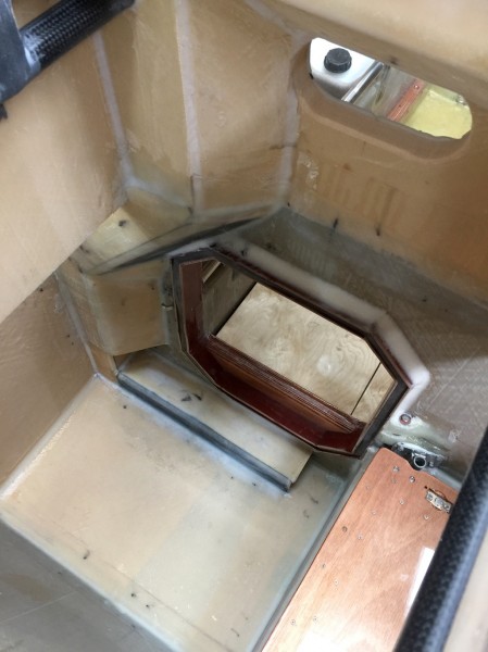
One channel under construction

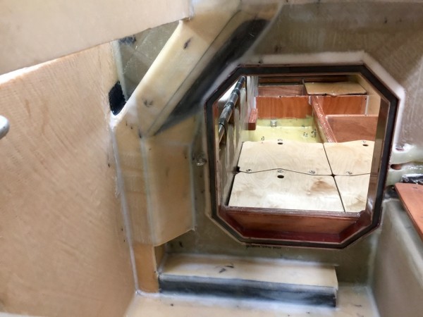
Vieuw from hatch. The two inlets one on each side.

Viuw from aft window looking into sleeping room through waterproof hatch.

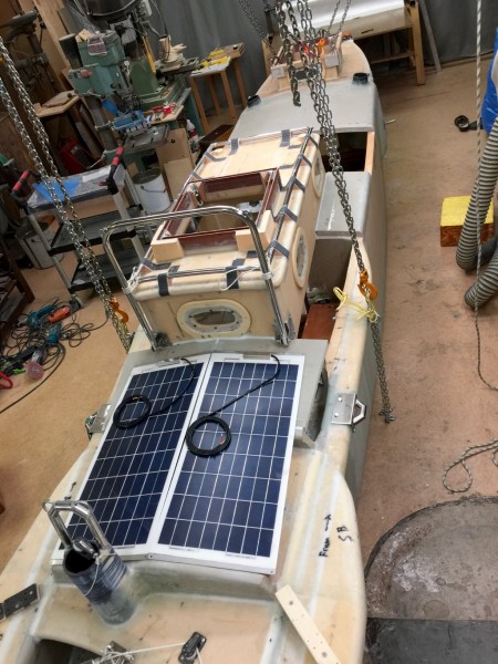
The main deck house. The solar panels are temporarily there.

To be continued…

Regards Yrvind

MORE PROGRESS

Here are the latest pictures.

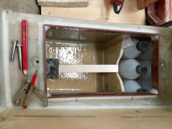
Below is the lunchbox or foodbox with food for about a week. The picture shows the six one-liter bottles. Seven would have been better, but such was unfortunatly not the geometry. Later musli and sardines will be added.

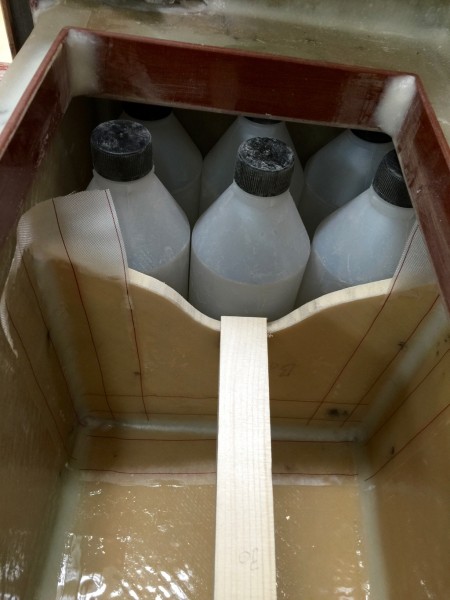
Close upp of the bottles that got there own compartment as not to rattle around. Its a good fit. The peelply has now been peeled and the stick that holds the wall in place taken away.

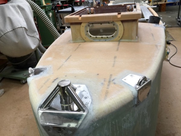
In the front of the boat the small deckhouse is now laminated into place and a towing bollard and four strong points are installed.

Close up.

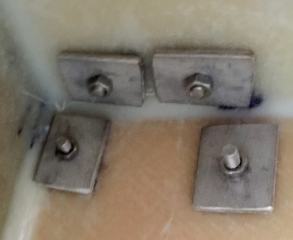
The strongpoints are boulted by 4 M6 boults good enough to lift the weight of several Ex Lex boats.

Inside are 3X4 cm backing washers.

The towing bollard is fastened by 5 M6 boults and 4 4.8 mm seelf tapping screws

There are also several extra laminations inside and outside to reinforce.

To be continued…

Regards Yrvind.

WINDOWS

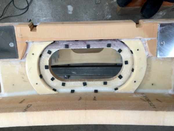
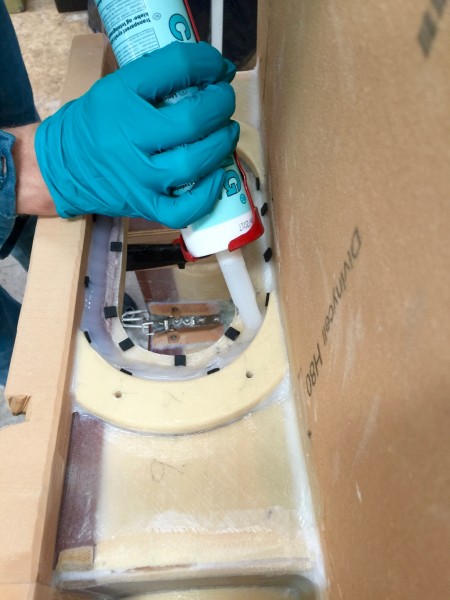
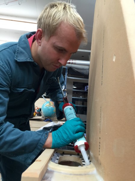
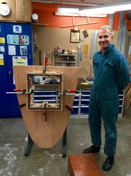
The windows in the forward deckshous are now in place thanks to Petter and G A Lindberg ChemTech AB.

I chose silicon becouse it is resistent to UV-light and weather. Butul and other componds may be stronger, but silicon holds 20 kilo in tension at each square centimeter giving a total strenght per window of about 4 tons wich is ample for a boat of about one ton. Also unless I go crazy the the force is unlikely to come from inside the boat.

Below are some pictures click once or twice to enlarge.

Rubber distances are placed to get the silicon acces to everywhere. This is important so that no hard spots get in contact with the tempered glass.

And last picture. Petter can relax after my harsch supervision.

To be continued…

Regards Yrvind

THE LEEBOARD ANGELS

In contrast to a centerboard can a leeboard be angled to give an optimum perfomance.

Consulting Matt Layden who knew a bit about the subject I have chosen 1 degree toe in and 12 degrees outward.

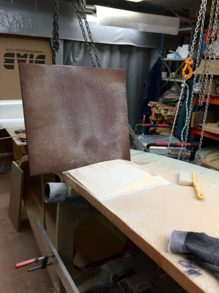
Tjat the board may rest agains a flat surface I have used sandpaper on a big particle board. Heavy work, but good results. Foto below.

This is how the angels came out after lamination with 8 layers 450 gram stiched glasfibre.

Leeboard up. The clamp will be replaced by a M 20 bolt and diameter 100 mm, 6 mm thick washer.

Leeboard down. This is the starboard side. Port side to be done.

To be continued…

Regards Yrvind

PROGRESS

There has been some progress. Things are finding there places.

Below the forward mastholders.

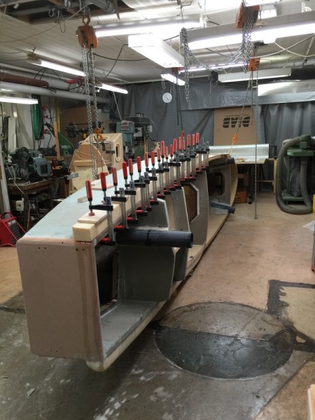
and aft mastholder. It was meant thet there should be one on each side also aft but unfortunatly it interfered with the two stearing lines, so one it is. It should have been at center but that interfered with the locker for the 15 kilo SPADE anchor so it is a bit offset to port.

There will be solar panels aft the main deck house. I do not like to walk on them so a rubrail on each side is added to take me back to the cockpit with its sculling oar and swim ladders.

The hardware to hold the rudders and yuloh is now fabricated.

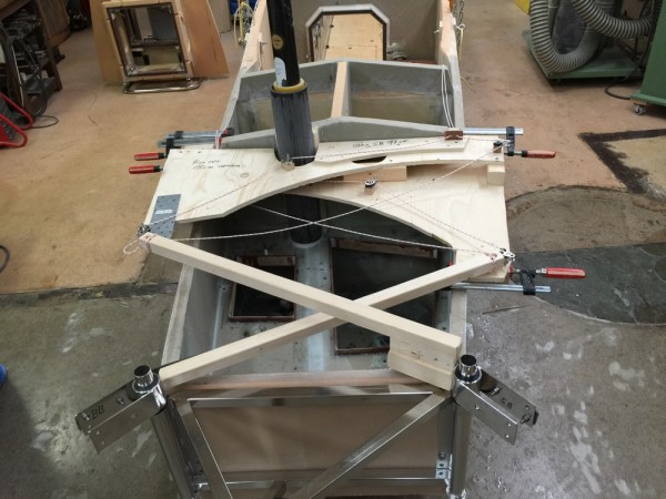
The picture below show the mock up for the control lines.

My intention is to use the twin rudders in lieu of a drouge by angling them out. I must thus be able to control them individually. The idea of a connecting bar did not work to my satisfaction.

Becouse the rudders are at the side the tiller have to be angled at 20 degrees or so invards to give the lines scope to pull.

The control lines run the lenght of the boat making it possible to adjust them even from bed.

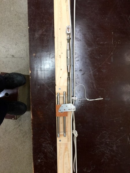
Below is a picture of my system for microadjusting them using a rigging screw. That system is sliding so that when courser adjustments are desired the thing can be mowed back or forth on a track. To get the lines from outside to inside seals are used running in pipes more about that later.

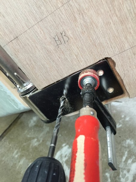
The rudderheads are now made and installed. They are about 5 cm thick. I could not use my drill press.  To be able to drill stright I looked at the mirror image of the drill in the fitting, when it was lined up with the the drill I was at right angle. Picture below.

Below is a picture of the rudders folded up.

The picture below show the rudder in the down position. The nut on the 20 mm bolt is welded to a wheel thuse making it easy to loch the rudders in the desired up or down position. The wheel is secured with a piece of string. Click on the picture once or twice to enlarge.

The rudders are rather large to get a lot of surface when using them as a drouge. Its nice to have control when running before a gale.

Here is a picture of the yuloh

Bengt Linden a supporter from Stockholm have also been visiting me.

Below next to the yellow boat that I sailed to Martinique with 2011.

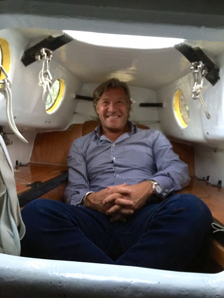
Below inside the boat.

Bengt is bigger than me.

To be continued…

Regards Yrvind

YRVINDS SURVIVAL SEXTANT EXPLANITION AND HOW TO USE.

To invent a small cheap functional sextant capable of measuring any angel up to 90 degrees and accurate and rugged enough for life raft use my thinking went like this. I imaged a fixed angled Bris sextant, then one more to the left having a slightly smaller angle a third one to the left of that with an even smaller angle and so on down to zero. To the right I imaged a series of Bris sextant their fixed values kept increasing up to 90 degrees. After that I imagined the steps between them becoming smaller and smaller. After that still in my mind I glued them all together. Now I had a thought model of the finished product, one long sextant with twisted mirrors.

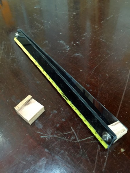
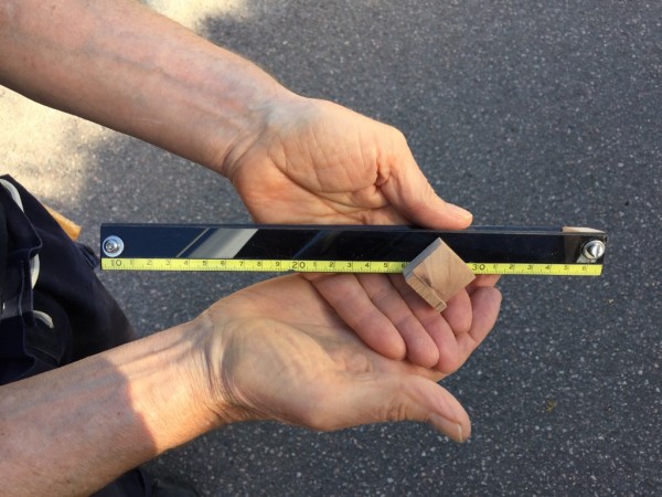
I made the first test by taking two strips of tinted semi reflecting acrylic glass and putting them together, one on top of the other. I joined them in one end, and then I twisted them at the other end to the desired angle and fastened them so together. I added a scale and a cursor to make reading easier because the human eye cannot focus so close. I have the option of adding shades to the cursor.

When taking a sight I hold the instrument close to my eye in a horizontal position, looking through it at the horizon. To move the image of the sun up and down I move my instrument sideways. When the sun is touching the horizon I note its sidewise position in relation to the scale and time it.

The next step is with the help of my position and the time to calculate the suns altitude. That way I find the corresponding altitude of my instrument at that point on the scale. I repeat the procedure for a few different angels.

As there are an infinite number of different angels there is no way I can calibrate them all, but that’s not necessary. It is enough to calibrate a few well spread out spots and make a table of them. To find any other angel I extrapolate or interpolate.

There is two ways to achieve the desired accuracy without a long and cumbersome instrument. One is to make a set of shorter ones, for example a set of three 30 cm long instruments with angels 0 – 30, 30 – 60 and 60 – 90, corresponds to a 90 cm long scale giving 1 centimeter for each latitude.

Eighteen instruments each 30 cm long will give a total length of scale of 5.4 meter long. Still the will require less space than a conventional sextant.

The other way is to make one instrument, like the Bris sextant with several mirrors that crate several images of the sun, spaced to the desired angels. It’s a neater solution but iterations or calculations will be needed to achieve the desired results.

The Bris Sextant and Yrvinds Survival Sextant are both interesting products and they complement each other. The Bris Sextant is extremely small and exact, but like a set of sockets has only fixed values. Yrvinds Survival Sextant is not so exact but can measure all altitudes a bit like an adjustable spanner.

Me, I have leave these experiments for time being to focus on my boat Ex Lex. Boatbuilding is also a lot of fun as is sailing the finished product.
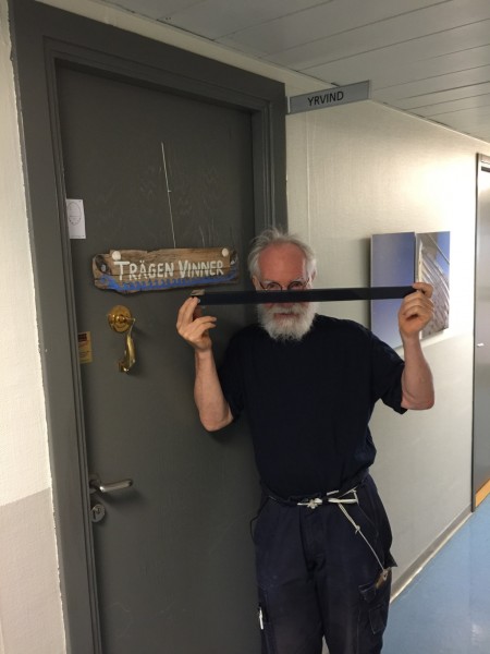
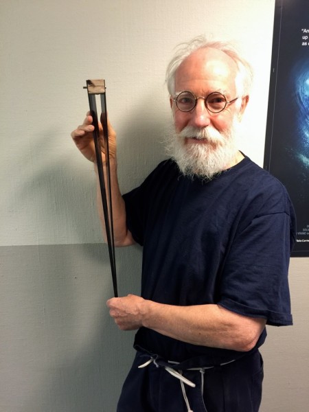
ABOUVE. Long version of Yrvinds survival sextant. To take a reading, slide the sextant sidevays, that will move the sun upp and or down. When the sun touches the horizon time it and note how far  sidevise the sun is on the scale. No moving parts.
To be continued…

Regards Yrvind.

YRVINDS SURVIVAL SEXTANT

Same years ago I invented the Bris Sextant as a backup. It’s a small cheap functional instrument. Its extremely accurate, much more so than the ordinary sextant because it uses a number of fixed angels instead of a continues scale, but like the ordinary sextant it needs accurate time to give you a fix.

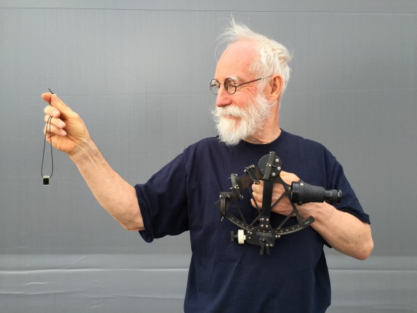
Photo above Bris Sextant in my right hand the ordinary in the left.

Time can be lost due to lightning, if there is a fire onboard and you most abandon ship, and for many more reasons such as the unlikely event of our civilization braking down and the time signals stops.

Fortunately latitude can be found without time by observing the suns altitude at noon.

The chronometer was invented only after most of the world had been explored so most discoveries were done without synchronized time. Therefore the explorers could not find their longitude. The going was though. They overestimated how far they had gone. Their latitude they could check, but not their longitude, hence maps from that time show the world much fatter. See illustration below.

To find ones destination without synchronized, one has to sail north or south to the latitude of the desired destination, then sailing east or west, constantly sounding and with a sharp lockout until one arrived at the desired destination.

Of course I could get an ordinary sextant but they are complicated and prone to errors, so I thought if I could invent a small cheap functional sextant with a continues scale, but without moving parts it would be a good thing.

An other picture

Photo above the survival sextant with its continues scale and its cursor.

Me with the first experimental model. I used it to testi if the new principel worked. It did and does but its accuracy is good enough for survival use.

I will soon publish an explanation of its principle and how to you use her.

To be continued …

Regards Yrvind.