DAGGER BOARD

Abouve two short videos on the dagger board trunk.

I am trying to learn how to splice them together to make longer videos but so far no succes.

I spend my time on the boat so there is not much time for this activity but I thought better a bit than nothing.

Progress is good but time consuming. Luckily the result exceed my expectaitions so I am happy.

To be continued…

Regards Yrvind

PAINT AND YOUTUBE

Thanks to Anders Jessen Watski Denmark and Katarina Frisell International Paint Sweden I now have paint for my boat.
Here is a link to a video I have uploaded on Youtube.

I used imovie. It was the first time and I think I made most of the mistakes one can make, but like sailing, experience and knowledge comes by practice. Give me a few years I will be better. I know it should be landscape format I know there should be sound. The sound was there yesterday but it seams to be gone now. There was also some fotos attached. I try again to fix it, but there is also much to do on the boat. and thats priority.

Tomorrow I will cut a hole in the deck and an other one in the bottom of the hull. It is the daggerboard case that will be fitted.

My reference from International Paint Company 1954. Click on the picture once or twice to enlarge.

I used to work for the International Paint company, in their laboratory as an assitant. The year was 1954. Below is a picture an reference.

Below a leaflet from an boat show 1976.

Leaflet from floating boat show 1976 Göteborg Sweden.

I will try to do more Youtube videos, slowly improving their quality. Their you can leave comments that I might answer if I have time. At this point I do not know how to add an subscription button but try I think that there is a way.

To be continued…

Regards Yrvind.

DAGGERBOARD

This is a video of the idea of the daggerboard.
It is placed foreward of the saloon/sleepingroom therefore it does not to any great extent interfere with living conditions.
When lowered there is space in the daggerboard case for the top of the daggerboard to mowe foreward thuse the bottom part can mowe aft creating the same effect as an crumple zone in a car. On the wind Exlex might mowe with 3 knots or 5 km an houer compared to 1oo for a car still the crumple zone about the same lenght.
Enjoy, regards Yrvind

GRINDING HATCHES

Here I get help of Stefan to grind the coamings flat.that will take the hatches, more precisely the gaskets of the hatches. The bottom of the  holders of the gasket is also flat bebouse I have poured NM-epoxy into it. Thus agot two very flat matching surfaces. That will make a thight hatch.

The hatch and the rim that will hold the gasket. Into the rim I have poured NM-epoxy that makes a leval surface.

To be continued…

Regards Yrvind

HATCHES

The hatches are on their way. Abouve is a video of me testing the waterproofness of one of the hatches.

No leaks not one drip even after 5 houers filled with water. In the video the hatch is upside down.

The hatches have taken a long time building, but for me this is part of a seawrthy boat. Together with the ventilation system and the well built boat this ensures that no water can enter the boat wathever the conditions even with the boat upside down. To have a boat that is always dry gives peace of mind, no reason to worry about storms, you know your boat can handle any weather.

Below are pictures.

The mold for the coaming is made from styrofoam.
Starting to build the mold for the part of the hatch that will hold the gasket.
The mold done and waxed.
The idea is that the gasket is not glued in placed. It just fits very tightly. Therefore no problem of changing the EPDM-gasket made of foam. The disadvantige in production no release angle of the moald. The mold is only good for one piece.
Now the hatch is getting nearly ready, the Divinycell is laminated with NM-epoxy. The corners are being reinforced with carbon fiber to hold the clamp down screws. The gascet is in place covered with a Nylon vacuum bag to prevent NM-epoxy to fill the place where it lives.
I am doing oversize bronze nuts to help align the gaffs that takes the M8 clamp down screws.
One of the gaffs being aligned.
To make sure that the bottom of the gasket holder is flat I have poured a bit of NM-epoxy in the holder. Nothing is as flat as hardened NM-epoxy.
Fitting and laminating the inner coaming of the aft hatch.

Hopefully more about the hatches will be on this website to make it more clear.

To be continued…

Regards Yrvind.

If you like my work please contribute.

A QUESTION FROM FINLAND

A QUESTION FROM FINLAND


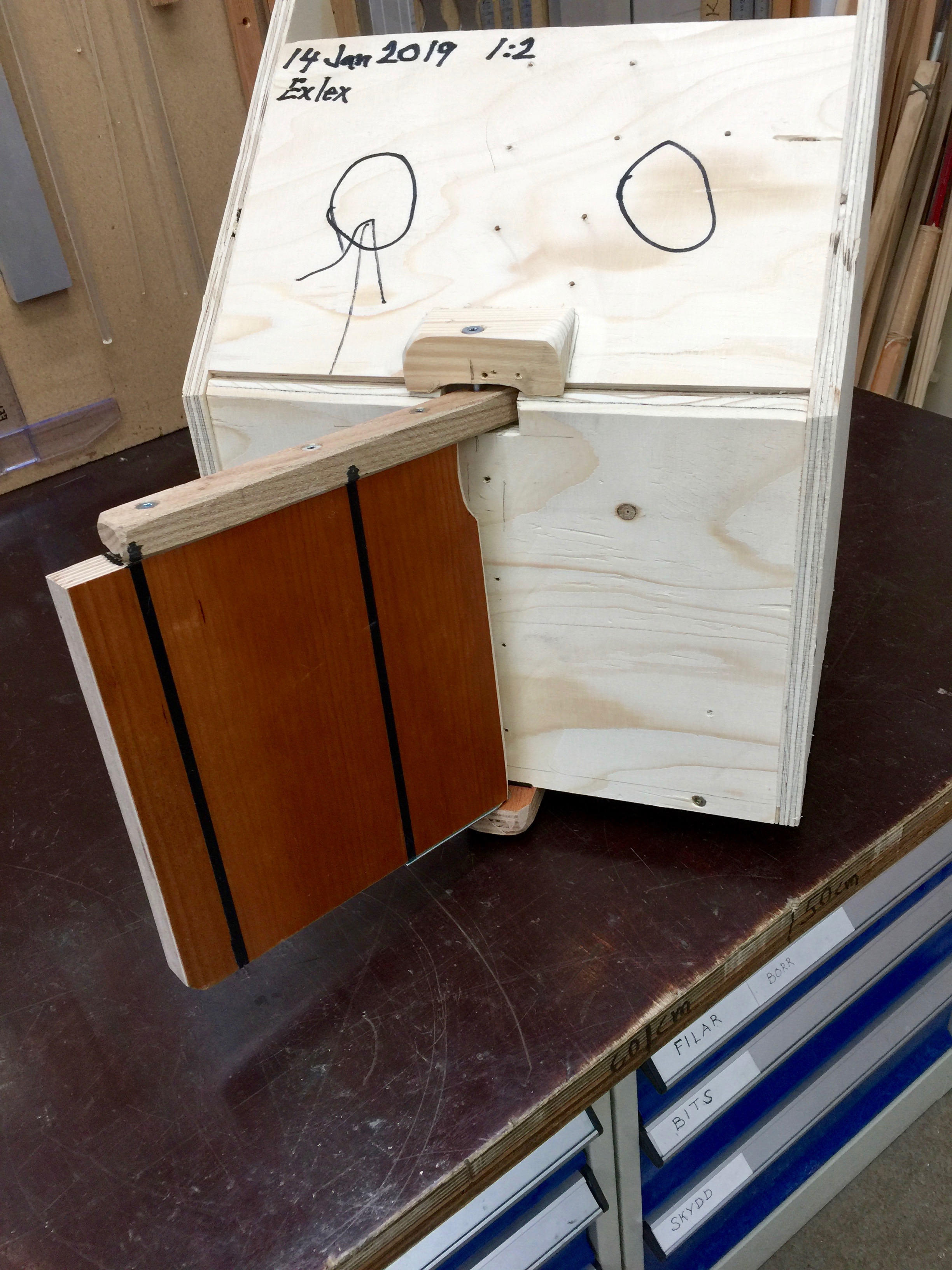
He ask if it is not better to have more dense material in rudder and centerboard as not to stability due to flotation.


Yrvind answer:

Heavier materials low down will give more stability. Added lead will give even more stability. In the case of the centerboard, when the board is raised, more weight will make the boat lose stability.

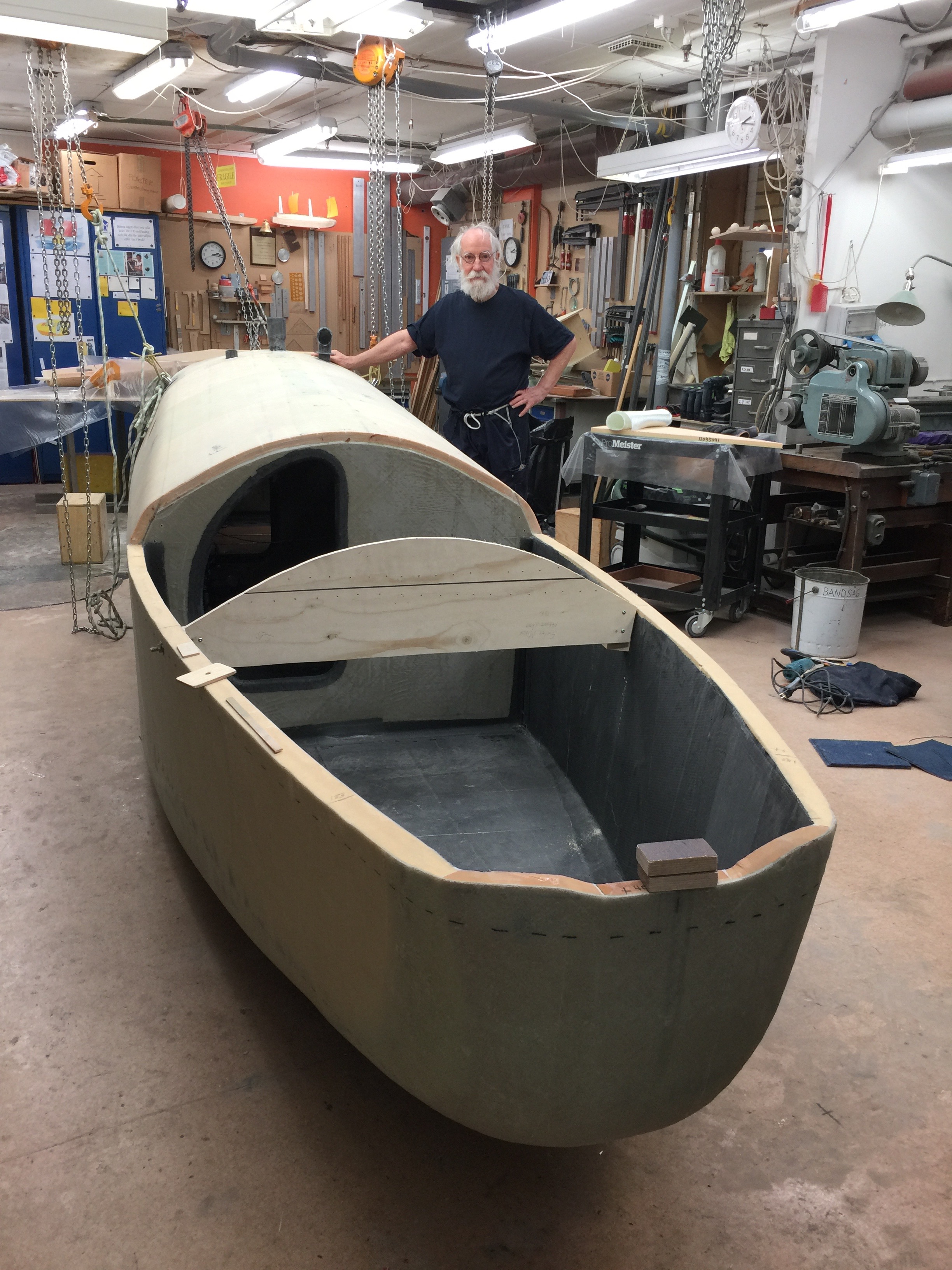
Almost every boat is designed as if it was to be a racing boat and the same with books about yacht design. Exlex is intended for cruising, when cruising I sail mostly down wind, even though I plan to round Cape Horn, 50° south to 50° south, east to west. Exlex is designed as a low energy boat and cruise at low Froude numbers around 0.3 this reduces the energy needed to about 1/6 of a conventional boat. See my Manifesto for a more detailed explanation.

More weight in the appendices will put more strain on them; they have to be designed more heavily. This added weight would make the boat slower down wind. It will also make the boat bigger and heavier and more expensive.

I think most boats are sub optimized for windward work. Neither do I think a cruising boat shall have weather helm.

Regards Yrvind

WORK ON CB AND RUDDER

Here is a report on the progress on work on the rudder and centerboard.

Some photos below.

I used a NACA- profile with a cord of 400 and 40 beam. To simplify I used a piece of the rudder from my chinerunner I 2011 sailed to Martinique with. I had made the rudder rather long and this is a bit I had cut of. Even this rudder and CB is long, but it is very easy to cut of a bit and difficult to add so in my experiment I make the fins a bit long. I have glued a pice on the aft end and put 3 strips of masking tape at maximum beam to add 0.7 millimeter to make it lay flat on my table saw. Mowing the fence and raising the blade to touch the rudder piece I got a guide that helped me to copy and get a new NACA profile. With this help I cut the Divinycell after that I used a pen to mark the bottom of the cut then grinding away the rest.
Peter was kind enough to help me.
A side viuw.
From a different angle
Laminating, using NM-epoxy 3 layers 450 gram glas + one extra layer from the root halfway down. The Divinycell is H130 130 kilo a kubic meter. The work went fine.
Rudder and center board paiteintly waiting for more work to be done on them.

To be continued…

Regards Yrvind.

Please help to support my project. Kindly donate money on pay pal or Swish.

DECK NOW DONE ON OUTSIDE

The deck is now laminated on the outside. Inside I have to do the fillets and taping so the boat is now uppside down once more.

I have also weighted the boat she came out at 426 kilos. That is to my liking becouse her waterline is 5.5 meters or 18 feet. There is not much more to add except the rudder and centerboard the hatches and a few odd and ends. Anchor and lead batterys will also add weight but a guess is that the painted boat will be about 600 kilos me and food and water for 60 days will add about 200 more kilos. To me it seams reasonable the she will weigh about 800 kilo at the start of a ocean passage. That gives a displacement ratio of 137.  Most cruisers land somewhere between 300 and 450 at the start of a passage, racers are lighter. The figure for to be able to plane given is belov 150. There are of course other criteria for to be able to plane as a suitable hull form. I think Exlex minor has such a hull. Where she does not shine is sail area to displacement, but wind pressure increases with the square of wind speed. Given enough wind and down wind she might be able to plane, but that is speculation. Hopefully I might find out coming summer.

Me in the fore hatch from where I can handle th fore sail. A tunnel through my bedroom and the saloon leads to the aft hatch from witch I can handle the aft sail. A safe lay out for a man born 1939.
Weighing the boat Aft measurment 285 kilos Fore measurment 141 kilos Distance between points 299 cm I use that number if I like to calculate longitudial center of gravity.  426 kilos total.

To be continued…

Regards Yrvind.


PERCEIVABLE PROGRESS

I have been working on the ventilation systems for weeks adding piece to piece usually six a day to the ducts. The two ducts for incoming air and outgoing each cross the boat just below the deck two times, then incoming air is ducted down to the bilges outgoing air ducted from bilges up to the deck. There is also water seals to prevent air escaping but letting spray out. This work is not really visible , but it is done and I am finished with it and I am happy about that becouse it has been drawn out and made me work long houers. Also done is most of the work in my sleeping room and in the aft saloon.

The fore deck on the other hand have been done in a few days and have changed the look of the boat very much.

Below a few pictures.

One mold to help to give the shape of the fore deck.
Me mixing NM-epoxy. Magnus who took the picture helped me to lift on the fore deck.
The piece in position, wighted down. Next work is shaping the fore deck and then laminating it. The inside surface is already laminated. That was done on the table.

To be continued…

Please help my progres by donating.

Regards Yrvind

NEW SEAL FOR TILLER

One reason I did a restart on Madeira was that the stering system jammed. Here is a better and lighter system. The rudder head has two pintles. The upper one is through the tiller and to the transom. That way the hole for the tiller to enter the cabin is minimal and easily sealed with a bellow. The picture show a model scale 1:2 of my transom. The two round rings indicate the windows.
This picture is more from the abowe. The torx screw on the transom indicates the pintle.

There will also be an outside tiller abouve for sheet to tiller and maneovring in tight places.

Four strong points have been added.
The hull is reinforced with several extra layers of glassfibre in NM-epoxy on inside and outside. There is large backing plates for the six M6 screws on the inside.
The strong points is made of 25 mm pipe. This helps to prevent chafe on ropes. I can lift the whole boat on any of the strong points. The two on the transom will be used in gales to tow chains. I have not used this technique before nor heard of anyone else using it but for a small boat I beliwe it is a good idea. Anywhay there is chain aboard for the anchor. The aft strong points is wery easily reaching standing in the aft hatch. No need to go on the deck. That would be cumbersome.